Monday, April 30, 2012

TCP/IP TO UART CONVERTER (TTL)

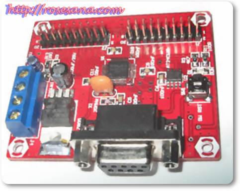
TCP / IP CONVERTER TO UART converter module is a 2-way serial UART to Ethernet-based WIZ105SR. This module can be used for TTL to Ethernet converter, RS-232 to Ethernet or RS-485 to ethernet. This module is properly used for LAN-based Presence system with a computer as a database server and sensor monitoring via LAN.

Specifications:

  • WIZ105SR based modules (Serial to Ethernet Gateway).
  • W5100-based and GC89L591A0 MQ44I.
  • Supports TCP, UDP, IP, ARP, ICMP, MAC, PPPoE.
  • Auto sensing 10/100 Base-T ethernet.
  • Auto MDI / MDIX.
  • MAG JACK is available for connection to a LAN network cable.
  • UART TTL serial interface 3.3 V.
  • Data transfer speeds up to 230 kbps.
  • WIZ105SR UART configuration can be selected on the software with the help of WIZ105SR Configuration Tool.
  • Baudrate: 1200 bps-230 kbps.
  • Data: 7 or 8 bits.
  • Parity: none, even, odd.
  • Flow Control: none, XON / XOFF, CTS / RTS.
  • RS-485 UART connection does not provide a connection flow control CTS / RTS.
  • There are three types of two-way conversion of the UART TTL to Ethernet, UART RS-232 to Ethernet and UART RS-485 to ethernet.
  • Equipped with a series of level converter 3.3 V to 5 V for TTL UART interface.
  • There is a blue 3 pin connector for RS-485 termination (COM, D +, D-) to facilitate the installation of cables for RS-485 interface.
  • There is a reset button to refresh the client-server connection.
  • Available factory reset button can be used to restore all settings to the initial conditions WIZ105SR module (default).
  • Available indicator pin header for connection to a client-server.
  • 5 VDC power supply with two pin blue connector.
  • Compatible with DT-Low Cost AVR series and support the system microcontroller / microprocessor another.
  • Equipped with the Configuration Tool WIZ105SR, datasheet, manual, test program and schematic.
  • Dimensions: 8.4 cm  x 6.4 cm  x 3.7 cm 

Neo Stepper Motor 2.4A by SPC

Neo 2.4A Stepper Motor controller module is a round fruit with a stepper motor full step or half step. This module requires an additional controller that can control the motor. In addition, this module has been equipped with a Dual Full H-Bridge Driver, so this module can be directly linked to bipolar and unipolar stepper motors.

Specifications:

  • Based ATtiny2313 as a motorcycle driver's control center.
  • Based on the A3995 motor driver IC, so it requires no additional motor driver module.
  • Able to control a DC motor which has a voltage value 8VDC - 36VDC and a maximum continuous current consumption of 2.4 A.
  • Capable of controlling the motor in half step or full step.
  • Require an additional controller to move the motor.
  • Fully compatible with the microcontroller module DT-51 Series, AVR-DT or DT-Series Basic Series.
  • Has two types of interfaces for communication with the controller / microcontroller, the TTL UART and I2C.
  • The movement of a stepper motor: Continuous Run, Pulse Count Run, Brake and Stop.
  • Neo SPC working on Stepper Motor 2.4A 4.8 VDC power supply level - 5.4 VDC.
  • Pin input / output compatible with TTL and CMOS voltage levels.
  • Only use two channels of data to TTL UART interface (Tx and Rx) and I2C (SDA and SCL).
  • Can be cascaded up to 8 modules when using the I2C interface.
  • I2C address setting via software (I2C address setting can only be done through the UART-TTL interface).
  • Has pin-out configuration of 16-pin DIP 600mil, so the module can be directly linked to the project board, PCB hole, or the IC socket 16-pin DIP 600mil.
  • Dimensions: 5.9 cm x 3.1 cm x 1.7 cm 


Neo Stepper Motor 1.2A by SPC

Neo 1.2A Stepper Motor controller module is a round fruit with a stepper motor full step or half step. This module requires an additional controller that can control the motor. In addition, this module has been equipped with a Dual Full H-Bridge Driver, so this module can be directly linked to bipolar and unipolar stepper motors.

Specifications:

  • Based ATtiny2313 as a motorcycle driver's control center.
  • Based TB6612FNG as a motor driver IC, so it requires no additional motor driver module.
  • Able to control a unipolar stepper motors fruit or bipolar.
  • Able to control a DC motor which has a voltage value of 2.5 VDC - 13.5 VDC and maximum continuous current consumption of 1.2 A.
  • Capable of controlling the motor in half step or full step.
  • Require an additional controller to move the motor.
  • Fully compatible with the microcontroller module DT-51 Series, AVR-DT or DT-Series Basic Series.
  • Has two types of interfaces for communication with the controller / microcontroller, the TTL UART and I2C.
  • The movement of a stepper motor: Continuous Run, Pulse Count Run, Brake and Stop.
  • Neo SPC working on Stepper Motor 1.2A 4.8 VDC power supply level - 5.4 VDC.
  • Pin input / output compatible with TTL and CMOS voltage levels.
  • Only use two channels of data to TTL UART interface (Tx and Rx) and I2C (SDA and SCL).
  • Can be cascaded up to 8 modules when using the I2C interface.
  • I2C address setting via software (I2C address setting can only be done through the UART-TTL interface).
  • Has pin-out configuration of 16-pin DIP 600mil, so the module can be directly linked to the project board, PCB hole, or the IC socket 16-pin DIP 600mil.
  • Dimensions: 5.8 cm  x 3 cm x 1.7 cm 

Neo DC Motor 2.4A by SPC

Neo 2.4A DC motor controller module is a DC motor Full H-Bridge using the PWM (Pulse Width Modulation). This module also provides several frequency PWM and I2C and UART interface options for easy TTL interface with external modules.

Specifications:

  • Can be used to control the direction and speed of two DC motors.
  • PWM control method using a choice of frequency 21.68 kHz, 2.71 kHz (default), 338.8 Hz and 84.7 Hz.
  • Full motor driver chip-based H-Bridge A3995.
  • Each driver can divert up to 2.4 Amperes of continuous current.
  • The power supply module: 4.8 - 5 VDC.
  • Support the motor voltage 8-36 VDC.
  • There are two interface options:
  • TTL UART, with baudrate configuration of 38 400 bps, 8 databit, 1 stopbit, and without flow control.
  • I2C, with slave configuration and the bit rate of up to 50 kHz.
  • On the I2C interface, 8 modules can be connected together in an I2C lines.
  • I2C address setting in the software and is available 8 I2C address selection.
  • Connection module with an external circuit through the connector 16 pin DIP 600mil so it can be directly connected with the project board or PCB holes.
  • Equipped with two LED indicators of the condition of DC motors.
  • Equipped with a test program to TTL UART interface and I2C.
  • Dimensions: 6 cm x 3 cm x 1.8 cm


Neo DC Motor 1.2A by SPC

Neo 1.2A DC motor controller module can control 1- 2  DC motor with two different spin directions. This module requires an additional controller that can control the motor. In addition, this module has been equipped with a Dual Full H-Bridge Driver, so this module can be directly connected to the motor.

Specifications:

  • Based ATtiny2313 as a motorcycle driver's control center.
  • Based TB6612FNG as a motor driver IC, so it requires no additional motor driver module.
  • Able to control two motors individually / simultaneously with two different directions.
  • Able to control a DC motor which has a voltage value of 2.5 VDC - 13.5 VDC and maximum continuous current consumption of 1.2 A.
  • There are 4 levels to choose PWM frequency, 21.68 kHz, 2.71 kHz, 338.8 Hz, 84.7 Hz.
  • Motor speed settings are available through the duty-cycle.
  • Require an additional controller for SPC DC Motor 1.2A Neo can move the motor.
  • Fully compatible with the microcontroller module DT-51 Series, AVR-DT or DT-Series Basic Series.
  • Has two types of interfaces for communication with the controller / microcontroller, the TTL UART and I2C.
  • Only use two channels of data to TTL UART interface (Tx and Rx) and I2C (SDA and SCL).
  • Can be cascaded up to 8 modules when using the I2C interface.
  • I2C address setting via software (I2C address setting can only be done through the UART-TTL interface).
  • Has pin-out configuration of 16-pin DIP 600mil, so the module can be directly linked to the project board, PCB hole, or the IC socket 16-pin DIP 600mil.
  • Dimensions: 5.8 cm x 3 cm x 1.7 cm

Low Cost Motor Controller by SPC

Low Cost Motor Controller by SPC is the control module 4 DC motors or two stepper motors that are equipped with a driver that can be directly connected to a DC motor / stepper. Direction and speed control of DC motor 4 using PWM and direction and speed control stepper motors using the full step & half step. The module is equipped with TTL and I2C UART interface for ease of interface with other modules.

Specifications:


  • Can be used to control direction and speed of 4 DC motors or two stepper motors.
  • The motor driver circuit chip based on A3988 (Quad DMOS Full Bridge PWM Motor Driver).
  • Each driver can divert up to 1.2 Amperes of continuous current.
  • Supports unipolar stepper motors (configuration 5/6 cable) or bipolar (4 wires configuration).
  • Power supply: 4.8 to 5.4 VDC.
  • Support the motor power supply 8-36 VDC.
  • GND digital power supply lines and motor are separated by the chip EMI filter to minimize the motor power supply noise.
  • Methods of control direction and speed of a DC motor using PWM.
  • Methods of control direction & speed of servo motor using the half step and full step.
  • The selection of motors (DC or stepper motors) is done via configuration jumpers.
  • Equipped with two interface options:
  • UART TTL, with the configuration of 38 400 bps baud rate, 8 databit, 1 stopbit, and no parity bit.
  • I2C, with slave configuration and the bit rate of up to 50 kHz.
  • On the I2C interface, the 8 modules can be connected together in an I2C lines.
  • I2C address can be set in software without the jumper settings and options are available 8 I2C address.
  • Connections with external circuits using a 8x2 header with the size pitch (distance between pins) common (p = 1 "/ 2.54 mm).
  • Equipped with 4 LED indicators of the condition of the motor.
  • Equipped command to stop the rotation around the motor and simultaneously command the stepper motor to rotate by a certain number of rounds.
  • There are examples of programs using TTL UART interface and I2C.
  • Dimensions: 6.5 cm  x 4.1 cm  x 1.7 cm 

Sunday, April 29, 2012

FT232 USB Prototype

FT232 USB Prototype is a proto board module for the FT232R IC that serves as a UART to USB converter. This module can help in exploring all the capabilities of available FT232R for pin-out of the FT232R can be easily connected to an external circuit. In addition, this module has also been equipped with a series of power supply and mini USB port.

Specifications:

  • FT232R IC and IC-based converters MAX3232CDR.
  • Available USB port and port mini RJ-45 (RS-232).
  • Internal voltage regulator is available with choice of 2 output voltage: 3.3 VDC or 5VDC.
  • Capable of accommodating eight UART signals, Tx, Rx, RTS, CTS, DTR, DSR, CD and RI.
  • Protocol supports 8-bit data transmission / 7-bit, 1/2 stop bits, Add / even / mark / space parity, handshaking.
  • Supports data exchange speeds from 300 bps to 3 Mbps.
  • Internal receiver buffer of 256 bytes and 128 bytes of buffer trasmiter.
  • Proto board is available that allows you to put an additional circuit.
  • Can function as a USB to UART converter module RS-232 or USB to UART TTL.
  • Bit Bang features that can alter the function of 8 pin to 8-bit UART I / O.
  • There is a CBUS pin that allows you to transmit enable pin RS485, LED indicator, sleep mode, CBUS Bit Bang Mode, etc.
  • CBUS Bit Bang Mode allows for the use Bit Bang features along with a USB to UART converter through a 4-bit via the CBUS pin.
  • Dimensions: 10.2 cm x 7.6 cm x 1.8 cm

BASIC Stamp® BS2 Nano System

BS2 BASIC Stamp ® Nano System (PIC16C57) UART serial communication capabilities as well as Serial Downloading.BASIC Nano System has 32 ??bytes of RAM (12 I / O, 26 variables).

Specifications:

  • 2 Kbyte EEPROM that can accommodate up to 500 pieces of instructions.
  • Has a speed of 20 MHz processor to execute the program up to 4,000 instructions per second.
  • Has a 16 pin path input / output.
  • Available UART serial communication line RS-232 DB-9 connector.
  • Equipped with LED indicator programming.
  • Input voltage: 9-12 VDC and output voltage: 5 VDC.
  • Dimensions: 6.6 cm x 4.8 cm x 1.6 cm

BASIC Stamp® BS2SX Micro System

BASIC Stamp ® BS2SX Micro System (PBASIC2SX-28/SS) UART serial communication capabilities as well as Serial Downloading. BASIC Stamp ® BS2SX Micro System has 32 ??bytes of RAM (6 I / O, 26 variables) with the Scratch Pad for 63 bytes.

Specifications:

8 x 2 Kbyte EEPROM that can accommodate up to 4,000 pieces of instruction.
Has a speed of 50 MHz processor to execute the program up to 10,000 instructions per second.
Has a 16 pin path input / output.
Available serial communication line RS-232 UART with DB9 connector.
Equipped with LED indicator programming.
Input voltage: 9-12 VDC and output voltage: 5 VDC.
Dimensions: 6.6 cm x 4.9 cm x 1.6 cm

BASIC Stamp ® Mini system BS2P40

BASIC Stamp ® Mini system BS2P40 (PBASIC48W/P40) with Traffic serial UART and Serial Downloading. DT-BASIC Mini System also has 38 bytes of RAM (12 I / O, 26 variables) with 128 bytes of Scratch Pad.

Specifications:

  • 8 x 2 Kbyte EEPROM that can accommodate up to 4,000 pieces of instruction.
  • Has a processor speed of 20 MHz Turbo for the execution of programs up to 12,000 instructions per second.
  • Has a 32 pin path input / output.
  • Available UART serial communication line RS-232 DB-9 connector.
  • Equipped with LED indicator programming.
  • Input voltage: 9-12 VDC and output voltage: 5 VDC.
  • Dimensions: 6.6 cm x 5.6 cm x 1.6 cm

Friday, April 27, 2012

Low Cost Microcontroller System ver 2.0 with AT89S51


Low Cost Micro System ver 2.0 is a single chip microcontroller AT89S51 module with 4 Kbyte Flash memory and 128 bytes of RAM..


AT89S51 features Low Cost Micro System:

  • Two 16-bit Timer / Counter.
  • Full Duplex UART.
  • Watchdog Timer.
  • Dual Data Pointer.


Low Cost Micro System Specification ver 2.0:


  • MCS-51 variants supporting ® 40 pin include: AT89S52, AT89S53, AT89S8252, AT89C51, and AT89C52.
  • Has In-System Programming facility for ICs that support.
  • Have up to 32 pin path input / output.
  • Complete with 11.0592 MHz oscillator and has the ability UART Serial communication RS-232 are already completed.
  • Complete with a series of reset, manual reset button, and brown-out detector.
  • Using the input voltage is 9-12 VDC and has a voltage output of 5 VDC.
  • Requires an additional module DT-HiQ AT89S In System Programmer, USB DT-HiQ AT89S ISP, or DT-HiQ-51 USB AVR ISP to fill in the program code into the microcontroller.

Thursday, April 26, 2012

POS88-usb Thermal Printer

POS88 Thermal Printer is a high performance thermal printer. It can be widely used for real-time printing application.
POS88 is a high performance thermal printer. It can be widely used for real-time printing application, such as POS system, restaurant system, ATM, etc. POS88 can be connected with PC devices via usb port and is available for Windows 95/98/NT4.0 and 2000.

Features
  • Low noise, high printing speed
  • Easy use and maintenance
  • Marked paper and continuous paper available
  • Cash drawer control connector
  • Communication connector optional
  • ESC/POS compatible

AT89S51 Minimum System Ver 3.3

AT89S51 Minimum System Ver 3.3


AT89S51-based design with a fixed intelligent and resilient. MCS-51family Minimum System Ver 3.3 PCB design changes and use someSMD components thus making it more reliable and better quality.Component layout was slightly changed but still compact with the same PCB size as the previous version.


Technical Specifications:

PCB design is updated so that more reliable in suppressing noisefrom the power supply line and the noise caused by the influence of a magnetic field.
Based microcontroller AT89S51.
Serial port RS-232 interface standard for communication between computer and board Minimum System Ver 3.3.
Using a serial cable straight type. (version 3.0 using a serial cabletype cross)
8 Kbyte non-volatile memory (EEPROM) for storing programs anddata.
4 port input / output (I / O) with a capacity of 8 bits each port.
Port LCD with built-in routine (for character LCD with HD44780 driver/ compatible).
Works in two modes: download & stand-alone.
Expansion connector for connecting the Minimum System Ver 3.3with an add-on board that is compatible
Can accommodate the use of USB to Serial converter (which iscompatible UART serial modem).
Equipped with Loader Software for MS-DOS operating system andWindows.
Software Debugger DT51D equipped, with features: Free Run, StepOver, Trace Into, Memory Monitor, Watches & On-Line Help.
Dimensions: 10.3 cm x 8.4 cm x 1.9 cm

OEM Colour TFT LCD Monitor

This small OEM module has a 2.36" TFT colour screen with automatic PAL / NTSC.
Designed for integrators, it has a wide power supply range (5 to 12 Vcc) and low power consumption (120 mA @ 5 VDC).  It consists of a TFT screen with an associated control board connected by a flat flexible cable.
Key features:
  • Size 2.36 "(480 x 234 pixels)
  • Mode PAL / NTSC (auto switching)
  • Video input: 1 V pp (75 ohms)
  • Contrast: 150:1
  • Pitch: 0.1 mm x 0.1525
  • Power supply: 5-12 VDC
  • Consumption: 120 mA @ 5 VDC
  • Connection to 4-pin connector
  • Display Dimensions: 55.20 x 47.55 mm
  • Display Area: 48 x 35.6 mm
  • Control board Dimensions: 56 x 43.5 mm
  • CMUCAM 4 Compatible

Tuesday, April 24, 2012

DFRduino Player

The Player is able to play MP3/WAV/Midi sound track on SD card. It supports two interface UART/I2C which lets other microcontroller to talk to the player.
The player support both I2C and UART interface (via jumper). The play is thus able to controled by PC. A TTL/USB converter is required.

Specification

  • Supply Voltage:5V
  • Current:1000mA
  • CPU:Atmega 328P
  • MP3 Chip:VS1003
  • Interface:I2C/UART
  • UART:19200/8/N/1 (TTL level)
  • I2C Address:0x35
  • Output Power:2x3W
  • Support Media:MP3,WAV,MIDI
  • Support Meida Card:1 GB Micro Card
  • Support command: Pause/Next Sound/Previoud Sound/Play Sound/ Volume Control
  • UART/I2C Mode Switch


The interface mode of Player can be switched via the jumper.
The green led will flash once which means the player is under UART(Serial) mode when the player startup. The green led will flash twice which means the player is under I2C mode. Once the Player is ready the green LED will stay lit
I2C pin connection:
Analog Pin4 (SDA) goes to DO
Analog Pin5 (SCL) goes to DI

Support SD Cards


  • The player has been tested with micro SD card (1G).
  • The SD card must be formatted at FAT format, not FAT32.
  • If the green led is flashing all the time which means the SD card is not ready, either not supported or not corrected formatted. And string "\Plese check micro SD card\r\n" will be returned at UART mode.
  • If the green led do not flash, it means the SD card is working properly.


Support Commands

  • Pause Play "\:p\r\n" Return "pause\r\n" if success
  • Continoue Play "\:s\r\n" Return "start\r\n" if success
  • Play next "\:n\r\n" Return "next\r\n" if success,Return "false\r\n" if failed
  • Play previous "\:u\r\n" Return "key up\r\n"
  • Set the volume "\:v 255\r\n",set the volume, from 0 (minimum)-255 (maximum), Return "vol set ok" if success

ATTEN AT7328 dual channel 20MHz analog Oscilloscope

ATTEN AT7328 dual channel 20MHz analog Oscilloscope


specificatons:

VERTICAL AXIS 
Sensitivity
5mV~5V/DIV, 10 steps in 1-2-5 sequence (X5 MAG:1mV/DIV)
Sensitivity accuracy
≤3% (×5MAG: ≤5%)
Vernier vertical sensitivity
continuously variable to 1/2.5 or less of panel-indicated value
Frequency bandwidth
DC-20MHz (×5MAG:DC-7MHz)
DC-40MHz (×5MAG:DC-15MHz)
AC coupling
Low limit frequency 10Hz. (With reference to 100KHz,8DIV.Frequency response with-3dB)
Rise time
Approx.17.5Ns (×5MAG:Approx.50Ns) / 9.5nS (X5MAG: Approx.25nS)
Input impedance
Approx. 1M ohm//Approx. 25pF
Square wave characteristics
Overshoot: ≤5%(At 10Mv/DIV range) other distortions and other ranges: 5% added to the above value
DC balance shift: 5mV~5V/DIV; ±0.5 DIV, 1mV~2mV/DIV±2.0DIV
Linearity: < ±0.1DIV of amplitude change when waveform of 2 DIV at graticule center is moved vertically.
Vertical modes
CH1 single channel
CH2 single channel
DUAL
 CH1 and CH2 are displayed ALT or CHOP selectable at any sweep rate.
ADD
CH1+CH2 algebraic addition
Chopping repetition frequency
Approx.250KHz
Input coupling
AC, GND , DC
Maximum input voltage
300V peak (AC: frequency 1KHz or lower) When set probe switch at 1:1, the maximum effective readout is 40Vp p(14Vrms at sine wave); or set probe switch at 10:1, the maximum effective readout is 400Vpp(140Vrms at sine wave)
Common mode rejection ratio
50:1 or better at 50KHz sinusoidal wave.(when sensitivities of CH1 and CH2 are set equally)
Isolation between channels (at 5Mv/DIV range)
> 1000:1 at 50 MHz; > 30:1 at 20MHz; > 30:1 at 40MHz
CH1 signal output
At least 20Mv/DIV into a 50 ohm termination, Bandwidth is 50Hz to at least 5MHz.
CH2 INV BAL
Balanced point variation: ≤1DIV(Reference at center graticule)
HORIZONTAL AXIS
Sweep time
0.2μSec-0.5Sec/DIV,20Steps in 1-2-5sequence
Sweep time accuracy
±3%
Vernier sweep time control
≤1/2.5 of panel-indicated value
Sweep magnification
10 times
×10MAG sweep time accuracy
±5%(20nsec-50nsec are uncalibrated)
Linearity
±3%,×10MAG: ±5%(20ns and 50ns are uncalibrated)
Position shift caused by×10MAG
Within 2 DIV, at CRT screen center

TRIGGERING
Triggering source
CH1, CH2, LINE, EXT
Coupling
AC:20Hz to full bandwidth
Slope
+/-
Sensitivity
20Hz-2MHz: 1.0 DIV, TRIG-ALT: 2DIV,EXT:200Mv; 2MHz-20MHz: 1.5DIV; 20MHz or higher: 2.0DIV
TRIG-ALT: 3DIV,EXT:800mv
TV
Sync pulse more than 1 DIV (EXT:1V)
Triggering modes
AUTO; NORM; TV-V; TV-H.
(Both TV-V and TV-H synchronize only when the synchronizing signal is negative)

Input impedance
Approx:1M ohm//approx.25pF
Max input voltage
300V(DC+AC peak), AC: frequency not higher than 1KHz


X-Y MODE

Sensitivity
Same as vertical axis.(X-axis:CH1 input signal,Y-axis:CH2 input signal)
Frequency bandwidth
DC to at least 500KHz
X-Y phase difference
≤3°at DC-50KHz


Z AXIS
Sensitivity
5Vp-p (positive-going signal decreases intensity)
Frequency bandwidth
DC-2MHz
Input resistance
Approx. 47k ohm
Maximum input voltage
30V (DC+AC peak, AC frequency ≤1KHz)


CALIBRATION VOLTAGE
Waveform
positive-going square wave
Frequency
Approx,1KHz
Output voltage
2Vp-p ±2%
Output impedance
Approx,1K ohm


CRT
Type
6-inch rectangular type, internal graticule
Phosphor
P31
Acceleration voltage
approx 2KV
Effective screen size
8x10 DIV(1 DIV=10mm(0.39in))
Graticule
Internal
Trace rotation
provided