Wednesday, January 30, 2013

Robot Car Chassis UGV by Arexx

The Robot Car Chassis is a prototype of a robot car and designed for the classroom. The idea is to create a kit, cheap and simple enough for the classroom with enough educational value to challenge students for a semester. Most robots use a differential skid steer system, manufacturer decided to use a car chassis which provides the additional challenge of 3 point turns. The car is 75mm wide, 150mm long and about 60mm high. The large flat area at the front is ideal for adding a small breadboard.

Specification:

• Actuators / output devices: 2x DC brushed motors

• CPU: Atmega168 8Mhz
• Power source: 4x AA batteries
• Programming language: Arduino C++
• Sensors / input devices: Steering potentiometer, 4x IR line following sensors, 3-Axis accelerometer
• Target environment: Indoors, classroom

Micro Magician (micro controller) not included 

• Car is 75mm wide, 150mm long and about 60mm high
• Control Method: Autonomous / TV remote
• Operating System: Arduino IDE 0022

1000 watt DC to AC inverter + charger

1000 watt DC to AC inverter + charger


Technical specs:

  • input voltage 12VDC
  • output voltage 220VAC /50/60Hz
  • output power 1KVA /1000Watt
  • efficiency more than 75%

MSR-H01 Haxapod FRAME only Kit

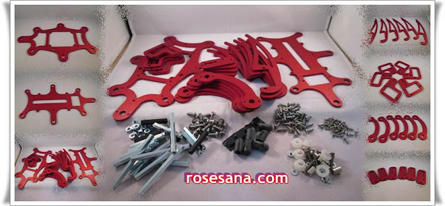
MSR-H01 is a 3 DOF hexapod kit consisting of 26 precision laser-cut 5053 aluminum body and leg components in one of three anodized colors: Silver, Red or Black. The kit comes with all screws, stand-offs, nuts and bolts for assembly (servos, electronics and batteries are not included).

The M3 & M4 machine screws included are high quality, stainless steel, hexagon button head type, with steel hexagon stand-offs. The top body plate has mounting holes for a p.Brain-SMB or SSC32 controller. With the electronics mounted underneath the top body plate, there is still enough room within the body for a 5 cell Sub-C battery pack. An optional PP3 battery holder can be fitted within the body frame for a clean, logic power supply. At the front of the hexapod there is a servo mounting point for an optional pan/tilt head.
Dimensions when standing: 280mm x 320mm x 175mm (LxWxH)

GPS/GPRS/GSM Shield V3.0 (Arduino Compatible)

GPS/GPRS/GSM Shield V3.0  (Arduino Compatible)


A GPS/GPRS/GSM shield from DFRobot. This shield with a Quad-band GSM/GPRS engine works on frequencies EGSM 900MHz/DCS 1800MHz and GSM850 MHz/PCS 1900MHz. It also supports GPS technology for satellite navigation. It's possible for your robot and control system to send messages and use the GSM network.
 
It is controlled via AT commands(GSM07.07 ,07.05 and SIMCOM enhanced AT Commands). And the design of this shield allows you to drive the GSM & GPS function directly with the computer and the Arduino Board. It includes a high-gain SMD antenna for GPS & GSM.
 
This GPS/GPRS/GSM shield uses an embedded SIM908 chip from SIMCom.Featuring an industry-standard interface and GPS function, the combination of both technologies allows goods, vehicles and people to be tracked seamlessly at any location and anytime with signal coverage.


Specification
  • Power supply: 6-12v
  • Low power consumption (100mA@7v - GSM mode)
  • Quad-Band 850/900/18001900MHz
  • GPRS multi-slot class 10
  • GPRS mobile station class B
  • Compliant to GSM phase 2/2+
  • Class 4 (2 W @ 850/900 MHz)
  • Class 1 (1 W @ 1800/1900MHz)
  • Control via AT commands(GSM07.07 ,07.05 and SIMCOM enhanced AT Commands)
  • Support GPS technology for satellite navigation
  • Embeded high-gain SMD antennas for GPS & GSM
  • Directly support 4*4 button pad
  • USB/Arduino control switch
  • Programmable switch for Arduino
  • LED indicators for power supply, network states and working status
  • Board Surface:Immersion Gold
  • Switches:
    • S1 -- Programming mode / Communication mode
    • S2 -- Controlling interface: USB / Arduino
  • Interfaces:
    • Embedded SIM card holder
    • Speaker & Mic Jack socket
  • Size: 81x70mm
  • Specifications for SMS via GSM / GPRS
    • Point-to-point MO and MT
    • SMS cell broadcast
    • Text and PDU mode
  • Specification for GPS
    • Receiver 42 channels, GPS L1 C/A code, High-performance STE engine
    • Sensitivity:
      • Tracking: -160 dBm
      • Cold starts: -143 dBm
    • Time-To-First-Fix:
      • Cold starts: 30s (typ.)
      • Hot starts: 1s (typ.)
    • Accuracy:Horizontal position: <2 .5m="" cep="" li="">
    • Power consumption (GSM engine in idle mode):Acquisition 77mA,Tracking 76mA

Netduino Plus 2

The Netduino Plus is an open source electronics platform using the .NET Micro Framework. The board features a 32-bit microcontroller and a rich development environment, making it a perfect solution for engineers and hobbyists alike.
The Netduino Plus 2 has four times the speed (168MHz), six times the code space (384KB), and twice the available RAM (100KB+) of Netduino Plus 1. They've also given it a whole series of rich new features like four serial ports, six PWM channels and 12-bit ADC. The 6-pin ICSP header has been swapped out for a 10-pin MiniJTAG header. The goal is to enable developers to compile their own firmware using GCC and debug both native and managed code at the same time.

Specification
  • Atmel 32-bit microcontroller
  • Speed: 168MHz, Cortex-M4
  • Code Storage: 384 KB
  • RAM: 100+ KB
  • 10 mbps Ethernet
  • Micro SD card support up to 2 GB
  • Input Voltage: 7.5 - 9.0 VDC or USB powered
  • 25 mA per Pin max Current
  • Digital I/O are 3.3 V but 5 V tolerant

System requirements                                
Windows                                            
  ● Windows XP, Vista, 7 or 8 (32 or 64 bit) Recommended: Windows 7 or 8
  ● 1.6 GHz or faster processor
  ● 1 GB RAM
  ● Up to 3 GB of available hard drive space for Visual Studio Express 2010

Mac OS and Linux
  ● ParallelsSerial deployment and partial USB support Requires copy of Windows in virtual machine
  ● VMWare Fusion or Oracle VirtualBox Serial deployment and partial USB support, Requires copy of Windows in virtual machine
  ● Experimental Mono (native) support. Future native Mac OS and Linux support provided by an experimental open source project

processor and memory
  ●STMicro 32-bit microcontroller
  ●Speed: 168MHz, Cortex-M4
  ●Code Storage: 384 KB
  ●RAM: 100+ KB

digital i/o features
  ●all 22 digital and analog pins: GPIO
  ●digital pins 0-1: UART 1 RX, TX
  ●digital pins 2-3: UART 2 RX, TX/PWM
  ●digital pins 5-6: PWM, PWM
  ●digital pins 7-8: UART 3 RX, TX
(also works as UART 2 RTS, CTS)
  ●digital pins 9-10: PWM, PWM
  ●digital pins 11-13: PWM/MOSI, MISO, SPCK
  ●digital pin SD/SC: SDA/SCL
(also works as UART 4 RX, TX)

networking
  ●ethernet: 10 mbps
  ●network stack: lwIP

storage
  ●micro sd (up to 2 GB)
  ●auto card detect

power
  ●input: 7.5 - 9.0 VDC or USB powered
  ●output: 5 VDC and 3.3 VDC regulated
  ●max current: 25 mA per pin
microcontroller max current: est. 125 mA total
  ●digital i/o are 3.3 V--but 5 V tolerant

environmental
  ●operating temperature:
0 - 70 °C (32 - 158 °F)
  ●RoHS compliant

Monday, January 28, 2013

Kyoritsu 3132A Analogue Insulation / Continuity Tester

Kyoritsu 3132A Analogue Insulation / Continuity Tester

• Dust and drip proof construction. (designed to IEC 60529 IP54)
• Designed to meet IEC 61010-1 and IEC 61557 safety standard.
• 1mA rated test current at the minimum resistance.
• 200mA measuring current on continuity testing.
• Automatic discharge of circuit capacitance. (Any charge stored in the circuit under test will be automatically discharged after testing.)
• Live circuit warning buzzer and neon lamp.
• Small and lightweight. Shock resistant new case material.
• AC voltmeter with linear, easy-to-read scale.
• Operates on AA, R6P×6 dry batteries.


Insulation Resistance
Test Voltage250V/500V/1000V
Measuring Ranges
(Mid-scale Value)
100MΩ/200MΩ/400MΩ
(1MΩ) (2MΩ) (4MΩ)
Output Voltage
on open circuit
Rated test voltage+20%, -0%
Nominal Current1mA DC min.
Output Short
Circuit Current
1~2mA DC
Accuracy0.1~10MΩ/0.2~20MΩ/0.4~40MΩ
(Accuracy Guaranteed Ranges) ±5% of indicated value
Continuity
Measuring Ranges
(Mid-scale Value)
3Ω/500Ω
(1.5Ω) / (20Ω)
Output Voltage
on open circuit
4.1V DC approx.
Measuring Current210mA DC min.
Accuracy|±1.5% of scale length
AC Voltage
AC Voltage0~600V AC
Accuracy|±5% of scale length
General
Safety StandardIEC 61010-1 CAT.III 600V Pollution Degree 2
IEC 61010-2-031
IEC 61557-1/2/4
IP RatingIEC 60529-IP54
EMC StandardIEC 61326-1
Withstand Voltage3700V AC for 1 minute
Power SourceR6P (AA) (1.5V) × 6
Dimensions106(L) × 160(W) × 72(D)mm
Weight560g approx.
Accessories7122B (Test leads) Pouch for test leads
8923 (F500mA/600V fuse) × 2
R6P (AA) × 6
Shoulder Strap
Instruction Manual

Kyoritsu 3131A Analogue Insulation / Continuity Tester

Kyoritsu 3131A Analogue Insulation / Continuity Tester

The Model 3131A offers unmatched performance, and feature including test lead resistance zero adjustment for time-saving continuous operation, a clear ease to read illuminated scale, and a live circuit warning.
Test insulation up to 100MΩ at 250V, 200MΩ at 500V, 400MΩ at 1000V and continuity up to 20Ω.
LIVE circuit warning lamp plus audible warning.
Automatic discharge of circuit capacitance when TEST button is released.
Fuse protected (continuity range only).
Battery check LED.
Front panel zero adjust.
Back light function to facilitate working at dimly lit situations.
PRESS TO TEST button with lock down feature.


Insulation Resistance
Test Voltage250V/500V/1000V
Measuring Ranges
(Mid-scale Value)
100MΩ/200MΩ/400MΩ
(1MΩ) (2MΩ) (4MΩ)
Output Voltage
on open circuit
Rated test voltage+20%, -0%
Nominal Current1mA DC min.
Output Short
Circuit Current
1.3 mA DC approx.
Accuracy0.1~10MΩ/0.2~20MΩ/0.4~40MΩ
(Accuracy Guaranteed Ranges) ±5% of indicated value
Continuity
Measuring Ranges
(Mid-scale Value)
2Ω/20Ω
(1Ω) (10Ω)
Output Voltage
on open circuit
4~9V DC
Measuring Current200mA DC min.
Accuracy|±3% of scale length
General
Safety StandardIEC 61010-1 CAT.III 300V Pollution Degree 2
IEC 61010-2-031
IEC 61557-1/2/4
IP RatingIEC 60529-IP54
EMC StandardIEC 61326-1
Withstand Voltage3700V AC for 1 minute
Power SourceR6P (AA) (1.5V) × 6
Dimensions185(L) × 167(W) × 89(D)mm
Weight860g approx.
Accessories7122B (Test leads) Pouch for test leads
8923 (F500mA/600V fuse) × 2
R6P (AA) × 6
Shoulder Strap
Instruction Manual


MS6540B Infrared Thermometer


Features
lOptical Resolution (D:S) (30:1)
lWide temperature measurement range
lLaser target pointer
lReadout is ℉&℃ selectable
lTemperature Resolution: 0.1℃ or 0.1℉
lLCD with double temperature display and 4 bits
lMAX(highest), MIN(lowest),DIF(difference),and AVG(average) temperature display
lEmissivity adjustable (0.10 to 1.00)
lHigh-temp,and low-temp.alarm.
lData recording (record up to 100 group of data)
lResponse time: 500 msec
lLaser power: Less than 1 milli watt
lOptical Response: 8 um to 14 um
lWorking Voltage: 9V battery
lDimensions:Length 140×56×90
lWeight: 500g
lAccessories:Leather bag ×1.9V battery(6F22)×1


Specifications                                              
MS6540B
Temperature Range
-32℃~1050℃
-25℉~1922℉
Temperature Accuracy
>510℃
±1.5%
50℃~510℃
±(1.5%+1℃)
15℃~50℃
±(1.5%+2℃)
-32℃~15℃
±3℃
Temperature Resolution
±0.1℃ / ±0.1℉
Repeatability
±0.5℃ or ±0.5%
Distance to Spot (D : S)
30 : 1
℃ / ℉ Selection
Emissivity

Response Time
500ms
Laser target pointer
Data Logging
100 groups
Reading Hold
MAX, MIN,DIF,AVG
Temperature Alarm Setting
Display Backlight
Low Battery Display

MS6520B Non-contact infrared Thermometers

Non-Contact Infrared Thermometers

Features
lOptical resolution 10:1
lAutomatic range
lDual LCD Display
lMAXMINAVG value selectable
l/display selection
lBack light
lSingle-spot laser sighting
lHold function
lLow battery indication
lAuto Power Off

Specs:

Specifications                                              
MS6520B

Temperature Range
-20℃~ 500℃ ±(1.5%+2℃)
-4℉~ 932℉ ±(1.5%+4℉)
 
 
Temperature Resolution
±0.1℃ / ±0.1℉

Repeatability
±1℃

Distance to Spot (D : S)
10 : 1

℃ / ℉ Selection

Emissivity
0.95

Response Time
1 second

Laser pointer

Reading Hold

MAX, MIN, AVG

Display Backlight

Low Battery Display

Power Supply
1×9V 6F22 battery

Product Size
142mm×92mm×47mm/
5.6”×3.6”×1.9”

Product Weight
135g/0.3lb

Category
CE

DEKKO 550C contactless infra red thermometer

DEKKO 550C contactless infra red thermometer


Features:
  • Measuring Range : -40° C to 550° C
  • Spectral Response 6-14 uM
  • Display 3-1/2 digit with back lighting
  • D:S Ratio 8:1. has 90% encircled energy at the focal point
  • Accuracy ± 2°C or 2%
  • Diode Laser output Emmissivity 0.95 [Fixed]
  • Polarity Automatic
  • Operating Temperature 0° C to 50° C
  • Storage temperature -20° C to 60° C
  • Relative Humidity 10% to 90% rH
  • Power Supply 9 V battery
  • Automatic Selection range and Resolution 0.1° C
  • Built in Laser Pointer
  • Automatic Data Hold
  • ° C & ° F Switch
  • Back Light LCD Display
  • Auto Power Off
  • Unique flat surface, Modern Housing Design
  • Weight 130 GMS
  • Size : 86x46x160 MM
  • Comes with a leather soft carrying case