Friday, October 31, 2008

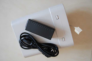
RAD HTU-2 HDSL Termination Unit


Using HDSL technology, HTU 2 extends the range of digital equipment up to 4.8 km (3.0 miles) over 24 AWG (0.5 mm), 4 wire copper cable. Using the HDSL repeater extends the range up to 8.4 km (5.2 miles) between the central office and customer premises.


  • HTU-2 eliminates the need for repeaters or optical cable in the last mile (local loop) or in the campus network environment.
  • Using advanced equalization, adaptive-filtering, echo cancellation technology and 2B1Q line coding, HTU 2 compensates for line impairments, bridge taps and mixed cabling. High immunity to background noise enables transmission of multiple HDSL lines via the same physical cable.
  • Two clock modes are available:
    • Internal - available only when the unit is configured as "CENTRAL". In this mode, the internal clock generator provides clock to the digital interface and the HDSL line.
    • External - available when the unit is configured as either "CENTRAL" or "REMOTE". In "CENTRAL" mode, the clock is recovered from the digital interface and passed to the HDSL interface. In "REMOTE" mode, the clock is recovered from the HDSL interface and passed to the digital interface.
  • Setup, control and monitoring of status and diagnostics information can be performed using one of the following:
    • Front panel LCD with three push buttons, using menu driven management
    • ASCII terminal connected to the async control port using command line interpreter
    • SNMP management station connected to the async control port, using Serial Link Interface Protocol (SLIP).
  • The priority bumping feature allows the user to select the timeslot priority (high or low) in case one of the HDSL lines is down.
  • HTU-2 is available as a standalone unit or as a rack mount card (HTU-2C) for the LRS-12 modem rack with SNMP management.
  • HTU-2 is available in AC version and can be mounted in a standard 19" rack using special hardware. One or two HTU-2 units can be mounted side-by-side.
Typical applications:
  • LAN-to-LAN connection
  • High speed data transfer HDSL
  • High speed Internet connection

Tuesday, October 28, 2008

Outdoor CPE with built in 48V PoE

Technical Specifications:
  • Ethernet Connection IEEE 802.3 100 BaseT (RJ45)
  • Standard 802.11 b/g (Wirelees Lan) IEEE 802.3 (Ethernet)
  • Operation Modes AP Client Router, AP Router, AP Bridge, PtP, and WDS Modes
  • PoE Power Adapter 48V/DC@ 400mA
  • External PoE Injector IEEE 802.3 (Ethernet)
  • Mounting Hose Clamp
  • Enclosure WeatherProof
  • Enclosure Integrated Antenna 14dBi Panel Antenna
  • Radio IEEE 802.11b/g
  • Temperature -40 to +80℃
  • Humidity 95% @ 55 ℃
  • Radome Material ABS, UV resistant Dimension 259 x 215 x 98 mm
  • Manual CD
  • Frequency Range 2.412 GHz - 2.4835 GHz Frequency Band N. America / FCC : 2.412 ~ 2.462 GHz (11 Channels) Europe CE / ETSI : 2.412 ~ 2.472 GHz (13 Channels) Japan : 2.412 ~ 2.484 GHz (14 Channels) France : 2.457 ~ 2.472 GHz ( 4 Channels) Spain : 2.457 ~ 2.462 GHz ( 2 Channels)
  • Security 64 bit/ 128 bit WEP, WPA, Port Filtreing, IP filtering MAC filtering, Port forwarding and DMZ hosting
  • Data Rate 802.11b ( 11Mbps, 5.5Mbps, 2Mbps, 1Mbps) 802.11b ( 54Mbps, 48Mbps, 36Mbps, 24Mbps, 18Mbps, 12Mbps, 9Mbps, 6Mbps)
  • Transmit Power RF Output Power : <>
  • RF Output Power : <>Receiver Sensitivity -80dBm (11 Mbps), -66dBm (54 Mbps)

Antenna Specification
  • 14dBi Panel Antenna
  • Frequency Range 2400 ~ 2500 MHz
  • Antenna Gain 14dBi VSWR 18 : 1
  • Max. Impedance 50 Ohms
  • Polarization Linear Vertical HPBW/ Horizontal 30 HPBW/ Vertical 30
  • Front Back Ratio 14dB
  • Power Handling 50 Watts ( CW )
  • Survival Wind Speed 216 Km/ Hr

Monday, October 27, 2008

SD GPS, sirf 3 + geohelix antenna

SD GPS, sirf 3 + geohelix antenna

Electrical Characteristics (Receiver)

Chipset : SiRF Start III
Frequency : L1, 1575.42 MHz
C/A Code : 1.023 MHz
chip rate Channels : 20 channel all-in-view tracking
Accuracy Position Horizontal : 10 meters, 2D RMS 1~5 meters, 3D RMS with WAAS, EGNOS corrected Velocity : 0.1m/sec Time : 1 micro-second synchronized to GPS time Datum Datum : WGS-84 (default)
Protocol GPS Protocol : NMEA 0183 (default)
GPS Output format : GGA(1 sec), GSA(1 sec), GSV(5 sec), RMC, 9600bps
Power Voltage : 3.3V Power Consumption : <95>

Physical Characteristics

Dimension : 62 * 24 * 2.1 mm
Weight : Approximately 15 grams
Optional Accessories Memory: Expansion Slot Micro SD card (TransFlash Card)
memory Size : 512MB, up to 2GB
Charging Seat: battery capacity 7~8 hour
Certification FCC, CE, RoHs
Bluetooth Specification ˙Bluetooth V2.0 compliant
Frequency Range: 2.402~2.480GHz
Receiver Sensitivity : -78dBm  

Mifare Wristband

Mifare Wristband is a RFID (Radio Frequency Identification) silicone wristband with two different sizes for adults and kids. The ergonomic design of Mifare Wristband makes it a comfortable, virtually imperceptible device to wear regardless of conditions. In addition, thanks to its waterproof specialties, it is ideal for applications like membership identification for gym club, payment for water activities, and so forth.

Mifare Wristband Specifications:

- MF1 S50
- MIFARE® Classic
- Operating frequency: 13.56MHz
- 1 Kbytes EEPROM
- Uses ISO 14443A transport protocol
- Color available: Blue
- Size: 202 x 17.5 mm

EM9962 RFID Keychain

Detailed Product Description
Key Specifications/Special Features:
  • Reading distance: 80mm
  • Based on GK4001 chip, with EM9917 reader
  • Operating temperature: -40 to 70 degree Celsius
  • Storage temperature: -40 to 80 degree Celsius
  • Material: ABS
  • Assembly: ultrasonic
  • Water resistance: yes
  • GK4001 (125kHz, 64 bits, R/O): yes
  • H4102 (125kHz, 64 bits, R/O): yes
  • I-Code (13.56MHz, 512 bits, R/W): yes
  • Mifare 1 (13.56MHz, 8Kb, R/W): yes
  • Temic E5557 (125kHz, 256 bits, R/W): yes
  • Hitag 1 (125kHz, 2048 bits, R/W): yes
  • Hitag 2 (125kHz, 256 bits, R/W): yes
  • Legic 256 (13.56MHz, 2048 bits, R/W): yes
  • Applications: door access control, burglar prevention, patrol management, personal identification, car park control, member club management

Wednesday, October 22, 2008

Smart Label - Contactless Label

RFID Label Smart Label LF / HF Contactless Label

  • Available Dimensions
    • Rectangular
      • 45X25mm, 28x45mm, 82x23mm, 54x85.6mm
  • Printing Method
    • Silkscreen
  • Number Printing Options
    • Ink Jet Number
  • Available Types
    • Paper Ticket with or without PVC/PET Top Sheet
    • Inlay(Transponder on PET substrate) with or without adhesive side
    • Adhesive labels of 0.55mm thickness on roll
    • PET transparent card of 0.55mm thickness
  • Storage Temperature
    • -25oC to +50 oC
  • Chip Available at 13.56MHz
    • ISO / IEC 14443 A
      • Mifare 1K S50 / MF1 S50, Mifare 4K S70 / MF1 S70,
      • Mifare 1K-Compatible, Mifare Ultralight
  • Key applications
    • Public transportation
    • Access management
    • Event ticketing
    • Gaming
    • Identity
  • Key features of Mifare 1K S50
    • 1 kbyte EEPROM (768 Byte free available)
    • Unique serial number (4 Byte)
    • 16 securely separated sectors supporting multi-application
    • Each sector consists 4 blocks with a length of 16 Byte
    • 2 x 48 bit keys per sector for key hierarchy
    • Access conditions free configurable based on 2 level key hierarchy
    • Number of single write operations: 100.000
    • Data retention: 10 years

PX-200 OEM-PIC kit2 Programmer

PX-200 OEM-PIC kit2 Programmer
Interface USB port and no need external power supply

Program target PIC microcontroller via ICD jack (compatible ICD2)

3 of LED status (POWER, TARGET and BUSY)

Upgradable Operating System firmware with Software

Includes :
PX-200 board with base, USB cable, ICD cable,
CD-ROM and Documentation.
Support Microcontroller (early 2007) :
Baseline Devices
PIC10F200, 202, 204, 206, 220, 222
PIC12F508, 509, 510
PIC16F505, 506, 54, 57, 59
Midrange Devices
PIC12F615, HV615, 629, 635, 675, 683
PIC16F616, HV616
PIC16F627A, 628A, 648A, 630, 631, 636, 676
PIC16F677, 684, 685, 687
PIC16F688, 689, 690
PIC16F72, 73, 74, 76, 77
PIC16F716, 737, 747, 767, 777,785, HV785
PIC16F84A, 87, 88, 818, 819
PIC16F870, 871, 872 , 873, 874, 876, 877
PIC16F873A, 874A, 876A, 877A
PIC16F883, 884, 886, 887
PIC16F913, 914, 916, 917, 946
PIC18 Devices
PIC18F242, 252, 442, 452,458
PIC18F1220, 1320, 2220, 2320
PIC18F2331, 2410, 2420, 2431
PIC18F2450, 2455, 2480
PIC18F2510, 2515, 2520, 2525, 2550, 2580,
2585, 2610, 2620, 2680
PIC18F4220, 4320, 4331, 4410, 4420, 4431,
4450, 4455, 4480, 4510, 4515, 4520,
4525, 4550, 4580, 4585
PIC18F4610, 4620, 4680
PIC18F6520, 6620, 6720, 8520
PIC18F8620, 8720
PIC18F6527, 6622, 6627, 6722
PIC18F8527, 8622, 8627, 8722
PIC18F_J_ Devices
PIC18F24J10, 25J10, 44J10, 45J10
PIC18F65J10, 65J15, 66J10, 66J15
PIC18F67J10, 66J60, 66J65, 67J60
PIC18F85J10, 85J15, 86J10, 86J15
PIC18F87J10
PIC18F86J60, 86J65, 87J60
PIC18F96J60, 96J65, 97J60
PIC24 Devices
PIC24FJ64GA006, 64GA008, 64GA010
PIC24FJ96GA006, 96GA008, 96GA010
PIC24FJ128GA006, 128GA008, 128GA010

Tuesday, October 21, 2008

PIR (Passive Infrared) Motion Sensor


PIR (Passive Infrared) Motion Sensor
parallax passive Infra Red Sensor for motion detector applications
Specs:
- Voltage supply : 5V
- detection range: 20 feets (about 6.7 meters)
- Output High Voltage : 5 V
- Settling time 10- 60 second
- Basic Stamp microcontroller compatible

Saturday, October 18, 2008

CMUcam KIT - boe-bot accessories

Track images with the Boe-Bot® Robot CMUcam! The Boe-Bot CMUcam ships with printed documentation, cd-rom with demo programs, and mounting directions. The Boe-Bot CMUcam (#30051) is designed specifically for the Parallax Boe-Bot robot. Download the complete manual and video at the bottom of the page for more detailed information.

The board communicates using a TTL level serial port and has the following functionality:

* Track user defined color blobs at 17 frames per second, find the centroid of the blob
* Gather mean color and variance data Arbitrary image windowing
* 80x143 resolution
* 9600 baud serial communication
* Automatically detect a color and drive a servo to track an object
* Slave parallel image processing mode off a single camera bus - advance function
* Ability to control 1 servo or have 1 digital I/O pin - advanced function
* Adjust the camera's image properties - advanced function.

The Boe-Bot CMUcam includes a printed user manual, cd-rom with sample code, and a pre-installed custom mounting bracket with two screws. There are other CMUcam kits available which may have different parts, features, and documentation that aren't designed to work specifically with the Boe-Bot robot.

1) The Boe-Bot Robot version of the CMUcam as shipped by Parallax cannot use the CMU PC Java code directly without modifications (and voiding the Parallax warranty)
The Boe-Bot CMUcam uses the same PCB as the general purpose package (described below) but does not include the parts that convert the serial port to RS232C levels compatible with a PC serial port. It also doesn't include the voltage regulator and jumper headers since they aren't required when using the BASIC Stamp microcontroller. This version can be modified for use with a PC by adding the parts that were left off the board, although the Parallax warranty is voided if you modify the board. While you cannot directly view a picture from the camera on your PC with the Boe-Bot CMUcam setup, a demo program is included that allows you to display the tracking data packets from the CMUcam on the PC debug screen. In some ways this is better than viewing a raw camera picture because you are seeing the data your robot will be using to "see" its world.

2) The regular version (non Boe-Bot robot specific version/not offered by Parallax) of the CMUcam directly supports the Java app on the PC.

A general purpose CMUcam PC evaluation package doesn't include the mounting brackets for the Boe-Bot robot. If you wanted to use this package with the Boe-Bot robot you would need to build a mounting bracket and remove the Max232 chip. Then you would have to add wires from the TTL level serial port to the Boe-Bot robot's BASIC Stamp module. You would also need to add wires to connect the CMUcam to the Boe-Bot robot's battery pack. One potential problem with this is that you can damage the CMUcam or BASIC Stamp module when using the TTL level serial port connection if the power to both is not turned on and off at the same time. The Boe-Bot robot version of the CMUcam can be modified to be the same as the non Boe-Bot robot version of the CMUcam then it will work with the CMU Java program (but voids Parallax warranty).

Technical summary of the above information:

In order to use the Java PC program the CMUcam needs to operate at 115,200 baud. The Boe-Bot robot version of the CMUcam is strapped to operate at 9600 baud only. You also would need to translate the TTL level serial port to standard RS232C levels for connection to a PC serial port.

Friday, October 17, 2008

ACR120 contactless smart card reader / writer

Sophisticated product from mifare/philips standard, ACR120 . Available in USB interface or serial interface, each with built in integrated antenna. ACR120 working in hi frequency , 13.65Mhz , ACR120 can read and write the iso card tag( mifare 1KB or mifare 4KB). Compact design with dimension 120mm x 73mm x 20 mm. Mifare Card Supported (DES Fire, Classics) and ISO14443 A/B. Running well in Windows operating system ( XP, 2K, ME, 98)

Contacless smart card reader & writer yang bekerja pada teknologi RFID 13.56MHz. Spesifikasi: - Dapat berfungsi untuk baca dan tulis. - Built-in antenna, frekuensi kerja 13,56 MHz. - Antarmuka:
RS-232 (serial) atau USB - Mendukung kartu Mifare (Classics, DESFire) dan ISO14443 A/B. - Wall mountable, dimensi 120mm (P) x 73mm (L) x 20mm (T). - Mendukung sistem operasi Windows 98/ME/2K/XP.

Saturday, October 11, 2008

ROBOTIX Education

ROBOTIX Education #1 Set (98570)

ROBOTIX Teacher's Guide Volume #1 (150+ Pages)
The Science of Robotics

• Introduction

• ROBOTIX Classroom Instructions
Beginning Lessons
Intermediate Lessons
Advanced Lessons
• ROBOTIX Computer Operating Instructions
• ROBOTIX Diagrams for Alternative Building Programs

Over 250 Universal ROBOTIX Parts
(1) 5-Switch Integrated Controller
(1) 2-Switch Controller
(1) 1-Switch Controller (Power Droid)
(7) Motors (High Speed)
(8) Power Cables (Yellow, Black & Blue "T")

ROBOTIX Computer Set (Hand-Held/Stand-Alone/Part #56) with Instruction Manual

Thursday, October 09, 2008

VX-Mega128 ATmega128 Microcontroller board

VX-Mega128 ATmega128 Microcontroller board

Support the ATmega128 with Flash memory of 128KB. Clock rate 14.7456MHz
34 I/O port of microcontroller are using INEX’s standard PCB-3 pin connector.
LCD16x2 module 4 of Button switches Binary Switch USB port (FT232RL).
ATmega128 pre-programmed Boot loader, programmable via USB port.
8-ch. Analog input with 10-bit Analog to Digital Converter
32KB RAM / 32KB EEPROM memory module plug on top
Support In-system Programming via ISP connector with PX-400 Programmer
Supply voltage +9V from external. +5V 500mA on-board regulator.

Includes : ATmega128 Microcontroller board, Plugable Memory module, USB cable, CD-ROM and Documentation.