Thursday, September 29, 2011

ACR88 pinpad smart card reader

The ACR88 PIN-pad reader is a versatile handheld portable smart card reader, featuring a built-in keypad, an LCD, a bi-color LED and a buzzer. Its capability for hosting non-volatile memory brings about better system support, whereas its onboard memory enables future firmware and application enhancements that guarantee against obsolescence. 

ACR88 is a line of secure pocket-sized electronic devices designed primarily for multi-applications. It is capable of performing secure authentication, displaying rich information from the card, and conducting online or offline transaction.

Furthermore, ACR88 is programmable through the ACR88 ScriptBuilder. With it, users can build their own standalone applications by following user-friendly and well-defined script commands provided by ACS. There is no more need to program the device in lower level languages or to deal with complicated hardware platform development. With ACR88 PIN pad reader, one can optimally realize the realm of possibilities that an application has in store!

Features:
  • Dual operation modes:
  • PC-linked: powered through USB
  • Standalone: powered through 3x AAA batteries
  • Accepts 3 V and 5V cards: two full-size cards and 3 SAM cards
  • Supports PPS (Protocol and Parameters Selection) up to 115,200 bps in reading and writing smart cards
  • Ergonomic and highly durable keypad
  • Easy-to-read, graphical LCD with backlight
  • Monotone buzzer with software controlled ON/OFF
  • 3 bi-color LEDs
  • Real-time clock (RTC) with independent backup battery
  • Field upgradeable for firmware (requires a firmware upgrade cable)
  • User Programmable for standalone program by using easy-to-use script commands
  • Supports Secure PIN Entry (SPE)
  • Tamper detection switch which acts as an indicator if there is any unauthorized intrusion
  • Hand-held size and weight
  • (Optional) Additional non-volatile memory for multilingual font storage


Applications:
  • Customer Loyalty
  • E-commerce
  • Health care project - medical identification
  • Online-payment device
  • E-government
  • Time and attendance

Technical Specs:

Dimensions175mm (L) x 76mm (W) x 31mm (H)
InterfaceUSB full speed
Power
PC-linked mode: automatically switch to USB bus power, always ON.
Standalone mode: automatically switch to 3 x AAA-size battery power, soft ON/OFF switch
Power ConsumptionLess than 100mA (excluding card power) in standalone mode
Backup BatteryIndependent backup battery (1 x CR2032) for RTC
Supply VoltageRegulated 5V DC
Supply Current< 60mA (without backlight and smart card)
Operating Frequency0-50°C
CLK Frequency3.58 MHz
Compliance/Certifications
  • ISO-7816 Class A and B (5V, 3V)
  • EMV Level 1, CE, FCC, RoHS Compliant
Operating System Support
  • Win 2000, Win XP, Win Vista, Win 7, Win Server 2003, Win Server 2008
  • Win XP x64, Win Vista x64, Win 7 x64, Win Server 2003 x64, Win Server 2008 x64, Win Server 2008 R2 x64
  • Mac
  • Linux

xbee 1mWatt module with U.Fl connector

xbee 1mWatt module with U.Fl connector
RF module that works on 2.4 GHz ISM band

specifications:
- Supply voltage 2.8 to 3.4 V
- U. FL connector for antenna connection
- Range 30m indoor or outdoor 100m (Line Of Sight)
- RF data rate of 250kbps
- IEEE 801.15.4 Protocol
- Transmit power output of 1mW (0dB)
- Sensitivity -92 dBm receiver
- TTL UART serial interface

For XBEE Pro 100mWatt click here

Caterpillar Robot Kit by Arexx

This is the Arexx Caterpillar Robot Kit. The Caterpillar is a unique robot that moves without wheels or legs. Precision ABS plastic parts and 8 micro servos allow realistic movement without complex programming. The transparent body is fitted with LEDs and looks great in the dark. The antennae changes colour when they touch an object.

This kit features roll sensor for self righting, 8 servos for realistic movement, sharp GP2D 12 can measure distance up to 1.5m away and give your robot infrared vision to avoid obstacles from a distance. This robot can move away from or investigate sounds. You can also add a second set of LEDs in a range of colours to brighten the appearance of your caterpillar.

Features:
• 8 DOF
• Can be programmed by the user
• Additional inputs for a wide range of sensors
• Moves without wheels or legs
• Precision ABS plastic parts and 8 micro servos
• Transparent body fitted with LEDs
• Sharp GP2D 12 measures distance up to 1.5m

Monday, September 26, 2011

Cisco - Linksys SLM224P 24-port 10/100 + 2-port Gigabit Smart Switch - SFPs/PoE

Cisco - Linksys SLM224P 24-port 10/100 + 2-port Gigabit Smart Switch - SFPs/PoE
A fast network switch doesn't have to be complicated. One of the Cisco Small Business Smart Switches, the Cisco SLM224P Smart Switch combines the best elements of Cisco premium managed switches under an intuitive, easy-to-use web interface. More than that, the SLM224P's copper network ports help ensure top transfer rates and limitless expansion opportunities.

The SLM224P bundles traffic-shaping capabilities into its assortment of features, prioritizing your network's high-bandwidth applications to deliver consistent, quality feeds for voice and video. Power over Ethernet (PoE) functionality is built in, reducing the cabling needed to run up to 24 connected network devices. An assortment of security protocols helps constrain your network to specific access levels, and a comprehensive logging system keeps tabs on your network's every move.

  • Additional features of the Cisco - Linksys SLM224P Smart Switch include:
  • A non-blocking switching capacity of 8.8 Gbps
  • Port-level security using 802.1x authentication and MAC-based filtering
  • Support for up to 128 port- and 802.1q-based VLANs

Thursday, September 22, 2011

AVRPLC16 v6

AVRPLC16 v6 is a AVR based PLC system with 8 opto-inputs and 16 relays (for currents up to 16A).
System can be placed in box allowing it to be used in moist and dusty environment. Design your AVR based control system very fast and easy.

AVRPLC16 v6 supports Telit GSM/GPRS modules: GM862-GPS, GM862-QUAD-PY and GM862-QUAD. These module can be easily mounted on-board via connector. Also they can be connected to GSM and GPS antennas.

Note: Telit GM862 GSM/GPRS modules, cables and antennas are sold separately.
Board is connected to Ethernet via on-board ENC28J60 (28-pin, 10BASE-T stand alone Ethernet Controller with an SPI interface).

This AVR board has USB 2.0 AVR programmer called AVRprog2. This USB AVR programmer doesn't use boot loader or any similar way of programming. The whole AVR memory and all pins are available for your application. Aside from that, this programmer is fast and easy to use InSystem programmer. This AVR Programmer is driven and powered from a single USB port on your computer. No additional AC power adapter is needed.

The programmer is recognized by Windows, which simplifies driver installation. The programmer board is specifically designed for In-Circuit Serial Programming (ICSP). Also External Programmer and JTAG can be connected with this PLC system, which allows external in-circuit debugging and programming of on-board AVR microcontroller.

Drivers for the on-board programmer are Microsoft® Windows® XP, Windows® Vista and Windows® 7 certified. The Windows certificate is a proof that the programmer supports mentioned Windows operating systems and is immediately recognized by the system, which guarantees correct Plug and Play functionality. Driver certification provides users with a wide range of benefits such as stable functioning, the ability to install and delete drivers without rebooting and compatibility with future versions of Windows.

The PLC System is packed in the protective box along with documentation and software CD. This box is very ressistant to any kinds of damages and shocks. Note: Telit GM862-GPS module with antennas and cables, UTP Cable, CAN-SPI board, MMC/SD card are sold separately.

Package Contains:
  • AVRPLC16 v6 PLC System with ATMEGA32 microcontroller
  • USB cable.
  • CD with software, drivers and examples in C, BASIC and Pascal.
  • Printed Documentation.
  • The Box is very resistant to shock and transport damage.

This product is shipped with fully functional demo version of mikroC PRO for AVR, mikroBasic PRO for AVR and mikroPascal PRO for AVR compilers. In Demo version, hex output is limited to 2k of program words. These compilers comes with selected examples for easier prototype development.

Saturday, September 17, 2011

RoBoard RB-100 Single Board Computer

RoBoard - the heart of robotics, making your robot more active and intelligent. This is not just a simple robot controller, but a truly computer based solution using the Vortex86DX, a 32bit x86 CPU running at 1000MHz with 256MB DRAM.

RoBoard allows users to install the Windows and Linux series O/S through the MicroSD card as bootable storage, allowing users to more easily develop PC based robotic applications. RoBoard is an advanced robot controller for advanced robot development and therefore makes an excellent platform for Microsoft Robotics Developer Studio development. There is also a code sample available to retrofit the Kondo Humanoid Robot with a RoBoard.

RoBoard RB-100 Features:
• Small dimensions: 96 x 56 mm!
• Fanless operation (Heat Sink included, pre-installed)
• Specialized Open Source VC++ Library
• Rich I/O interfaces for servo motors, sensors and more.
• 32 built-in PWM channels to control servo motors or other devices
• 8 24-bit general purpose input/outputs (GPIO),
• RS-232 serial, TTL serial, RS-485, USB V2.0 x 3
• 8 channels 10-bit Analog to Digital Conversion
• SPI/I2C bus
• Audio out & Microphone in
• 10/100M LAN
• Mini PCI socket for adding off-the-shelf Mini PCI components
• Power input range of 6V to 24VDC

Applications:
• PC based robotics
• Education
• Robotics research
• Home Automation
• Data logging and processing
• Wearable technology
• Tiny servers
• The Heart of your project!

Friday, September 16, 2011

Arduino Mega 2560

The Arduino Mega 2560 is a microcontroller board based on the ATmega2560 . It has 54 digital input/output pins (of which 14 can be used as PWM outputs), 16 analog inputs, 4 UARTs (hardware serial ports), a 16 MHz crystal oscillator, a USB connection, a power jack, an ICSP header, and a reset button. It contains everything needed to support the microcontroller; simply connect it to a computer with a USB cable or power it with a AC-to-DC adapter or battery to get started. The Mega is compatible with most shields designed for the Arduino Duemilanove or Diecimila.

Summary

  • Microcontroller ATmega2560
  • Operating Voltage 5V
  • Input Voltage (recommended) 7-12V
  • Input Voltage (limits) 6-20V
  • Digital I/O Pins 54 (of which 14 provide PWM output)
  • Analog Input Pins 16
  • DC Current per I/O Pin 40 mA
  • DC Current for 3.3V Pin 50 mA
  • Flash Memory 256 KB of which 8 KB used by bootloader
  • SRAM 8 KB
  • EEPROM 4 KB
  • Clock Speed 16 MHz

Thursday, September 15, 2011

ER2628 PROXIMITY READER

ER2628 PROXIMITY READER

Features

• 125 KHz typical operation frequency
• Reading of amplitude-modulated transponders
• Wide range compatibility with GK4001
• Long distance and fast response reading capability
• RS232 output/USB connectivity optional
• Dual-color LED and laud buzzer indications
• Very low power consumption
• D-Sub 9 pin connector and RS232 cable

Specifications

  • Power Requirements
  • Power supply: 12VDC, nominal
  • Operating voltage range: 8VDC – 18VDC
  • Absolute maximum: 25VDC
  • Current consumption: 29mA
  • Peak current: Less than 55mA


Functional

  • Reading distance: Up to 140mm
  • Reading response: Less than 0.1second
  • Accuracy: Less than 1 misread per 1 million


Operating Parameters

  • Visual indication, normal: LED red
  • Visual indication: LED green upon successful read
  • Audio indication: Buzzer beep upon successful read
  • RS232 baud rate: 9600baud
  • RS232 format: 1start bit, 8data bits, no parity, 1stop bit

Mechanical Sizes

  • Height x Width x Depth: 125mm x 100mm x 32mm
  • RS232 cable length: 1m
  • Weight: 150g

SIC-SKD7001

SIC-SKD7001 T5557 EM Encoder

Multipurpose RFID reader / writer with Windows application software for the low frequency RFID FDX series. This Simulator Kit Development (SKD) SIC-SKD7001 is used for evaluating and exploring various features of low frequency FDX RFID series from Silicon Craft Technology (SIC). The SIC-SKD7001 contains many essential functions for example reading, writing, accessing to a specific portion of data, etc. The SIC-SKD7001 will guide user/developer to quickly understand the operations and capabilities of the SIC FDX-RFID microchips. The SIC-SKD7001 is suitable for system integrators and hardware/software developers who have to be involved in the field of low frequency RFID.

specifications:
- Frequency: 100-150 kHz.
- Protocol: SIC.
- Modulation: Manchester, Bi-Phase.
- Data bit rate: RF/32, RF/64.
- Serial interface RS232 UART (USB Optional)
- Type of chip: SIC7771,

128x64 pixel LCD graphic with yellow green LED backlight.

128x64 pixel LCD graphic type STN transflective positive (yellow green) with yellow green LED backlight.

Technical Specifications:
- Built-in KS0107 KS0108 or equivalent controller.
- Number of dots = 128 x 64 dots
- View area = 62.0 (W) x 44.0 (H) mm
- Outline dimension = 78.0 (W) x 70.0 (H) x 14.3 (T) mm
- Dot pitch = 0.44 (W) x 0.60 (H) mm
- Input voltage = typ. 5.0 V.

128x64 pixel LCD graphic with white LED backlight.

128x64 pixel LCD graphic type STN transmissive negative (blue) with white LED backlight.


Technical Specifications:
- Built-in KS0107 KS0108 or equivalent controller.
- Number of dots = 128 x 64 dots
- View area = 62.0 (W) x 44.0 (H) mm
- Outline dimension = 78.0 (W) x 70.0 (H) x 14.3 (T) mm
- Dot pitch = 0.44 (W) x 0.60 (H) mm
- Input voltage = typ. 5.0 V.

Tuesday, September 13, 2011

GPS starter kit with LR9540 module

GPS Starter Kit is a means of developing OEM GPS receiver module based LR9540 (LR9548), equipped with LCD 16 characters x 2 lines as a medium of display. This module is suitable for developing applications related to GPS, such as: GPS navigator, GPS tracking, etc..
GPS Starter Kit has undergone a renewal in the use of the GPS module. In previous versions of the GPS Starter Kit uses a GPS module EG-T10, the current GPS Starter Kit comes back using the GPS module LR9540 (LR9548)

LR9540 (9548)
  • Chipset SiRFstarIII
  • Channel 20
  • Reacquisition 0.1 sec (avg)
  • Hot start 1 sec (avg)
  • Warm start 35 sec (avg)
  • Cold start 42 sec (avg)


Specifications:
  • Based LR9540 (LR9548), OEM GPS receiver module with 20 channels interface UART / TTL output and has a SiRF binary protocol NMEA-0183 &.
  • OEM GPS Receiver module supports other work on the voltage of 5 VDC and has a pinout accordingly.
  • Supports active antenna voltage is 5V and 3.3 V as it is equipped with a 3.3 VDC voltage regulator.
  • Available manual reset button and socket for backup battery 3 V sized 'CR2032'.
  • Equipped LCD 16 characters x 2 line LCD with 4-bit circuit and the LCD contrast level regulator.
  • Can be connected to a computer's USB port using the PC-Link USBer.
  • Requires 5 VDC power supply input.
  • Compatible and support the system microcontroller / microprocessor others.
  • Dimensions: 11.65 cm (l) x 10.45 cm (w) x 2.8 cm (h)


Equipment:
  • 1 piece GPS Starter Kit Board.
  • 1 Quick Start sheet.
  • 1 piece CD contains sample applications, datasheet LR9540 (LR9548), etc..

Monday, September 12, 2011

Serial Cable V35 to RS-232

Serial Cable V35 to RS-232
Specs:

  • serial communication
  • length 50cm / 100 cm
  • V35 female to db25 male

DEKKO 4070D handheld LCR meter


DEKKO 4070D Hand Held LCR Meter

Specifications:
  • 0.1μ H to 200H inductance measurement
  • 0.1pF to 20,000μF capacitance measurement
  • 1mΩ to 20MΩ resistance measurement
  • Dissipation factor measurement
  • Zero adjustment
  • Quick responding of measurement

Mastech MS6550B Infrared Thermometer

MS6550B Infrared Thermometer by Mastech, Contactless, wide range IR thermometer.


Features
lOptical Resolution (D:S) (50:1)
lWide temperature measurement tange
lLaser target pointer
lReadout is &selectable
lKTC/infrared thermometers selection
lTemperature Resolution: 0.1or 0.1
lLCD with double temperature display and 4 bits
lMAX(highest), MIN(lowest),DIF(difference),and AVG (average) temperature display
lEmissivity adjustable (0.10 to 1.00)
lHigh-temp,and low-temp.alarm.
lData recording (record up to 100 group of data)
lResponse time: 500 msec
lLaser power: Less than 1 milli watt
lOptical Response: 8 um to 14 um
lWorking Voltage: 9V battery
lDimensions:Length 140×56×90
lWeight: 500g    

Accessories
quantity

Standard K-type thermocouple(-40 to 260)
1

USB data cable
1
Standard
Data communication software(CD)
1

Leather bag
1

9V battery (6F22)
1
Optional
DC 9V power supply(7101-100mA)
1

Specifications                                              
MS6550B
Infrared Temperature Range
-32℃~1650℃
-25℉~3002℉
Infrared Temperature Accuracy
>510℃
±1.5%
50℃~510℃
±(1.5%+1℃)
15℃~50℃
±(1.5%+2℃)
-32℃~15℃
±3℃
Temperature Resolution
±0.1℃ / ±0.1℉
Repeatability
±0.5℃ or ±0.5%
Distance to Spot (D : S)
50 : 1
℃ / ℉ Selection
Emissivity

Response Time
500ms
Laser pointer
Data Logging
100 groups
Reading Hold
MAX, MIN,DIF,AVG
Display Backlight
Temperature Alarm Setting
Low Battery Display
K-type Temperature Range
-40℃~1370℃
-40℉~2498℉
K-type Temperature Accuracy
±(1.5%+1℃)
USB Interface (Windows OS)

Tuesday, September 06, 2011

DT-SENSE Color Sensor

DT-SENSE Color Sensor is a color sensor module Taos TCS3200-based sensors that can be used for the measurement of the RGB components of an object. DT-SENSE Color Sensor has the ability to save 25 color data as well as two options ie UART TTL interface and I2C. This module can be used for application of color or color sorting system of recognition.

Specifications :
  • TCS3200D Taos-based sensors.
  • Being able to measure the RGB color components of a colored object.
  • Equipped with a spacer of 3 cm so that it covers an area of view (field of view) 2 cm x 2 cm.
  • There are 2 white LEDs for help reading the color data on the object.
  • Available storage features 25 pieces of color data.
  • Pin input / output levels are compatible with TTL / CMOS.
  • Equipped with a TTL UART and I2C interfaces.
  • Configuration of serial communication are: baudrate 9600 bps, 8 data bits, 1 stop bit, no parity, and no flow control.
  • Bit I2C interface supports data rates up to 50 kHz.
  • In antamuka I2C module can be cascaded up to 8 modules without any additional hardware.
  • Hardware I2C address setting via jumper settings.
  • Available command to read the reference white balance and black balance and white colors to black reference read value via the command set.
  • Needs power supply from 4.8 to 5.4 VDC.
  • Available description and explanation of the command set supported by this module.
  • Available sample test program for the I2C interface.
  • CD / DVD-ROM contains a testing program, manual, quick start
  • Module dimensions: 4.8 cm (l) x 4.8 cm (w) x 2.8 cm (h).

DT-COMBO BASIC BASE BOARD

DT-BASIC BASE BOARD COMBO is a module basis for the development of AVR CPU Module series with several features such as path input / output, UART, I ² C and ADC. This module can be connected with the AVR CPU Module series for simple applications to complex. In this module available 2 pcs serial UART interface with a choice of 2 voltage level is RS-232 and TTL.

Specification :
  • Compatible with DT-AVR CPU Module series (up to 88 channels allocation of input / output).
  • 2 pcs RJ-11 connectors for UART interface with a choice of RS-232 voltage levels and TTL.
  • Available terminals to interface I ² C lines (SCL and SDA).
  • Available terminal for the ADC reference voltage input.
  • There are several options input supply voltage, ie 3.3 V - 5.5 V (without regulator) and 6.5 V - 12V (via a voltage regulator - on board).
  • LED indicators for voltage supply.
  • Capacitor using aluminum components and SMD components.
  • 10 pin connector / w housing for line input / output cabling so that errors can be avoided.
  • On each connector input / output available +5 V DC supply line that can facilitate the relationship with the application circuit.
  • 1 set of serial cable.
  • 1 piece DVD that contains a collection of manuals, schematics, and procedures for testing all products
  • DT-dimensional module BASIC COMBO BOARD BASE: 11.7 cm (l) x 9.8 cm (w) x 1.7 cm (h)

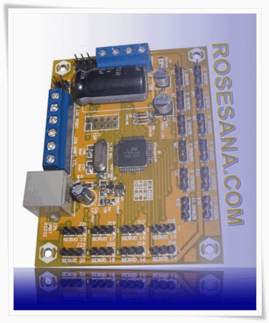
20 ports SERVO MOTOR CONTROLLER

20 ports SERVO MOTOR CONTROLLER is a servo motor controller module that can control up to 20 servo motors simultaneously or sequentially. This module supports the standard or continuous servo motors. SERVO MOTOR CONTROLLER SPC provides three interface options are TTL UART, RS-232 UART, and I2C. The module is equipped with software to design movement with a certain sequence and store the sequence of movements so that the appropriate applications for robotics and other applications that use other servo motors.

Specifications:
  • Can be used to control up to 20 servo motors simultaneously or sequentially.
  • Supports standard type servo motors and continuous.
  • Resolution of the servo control pulses of 1 us.
  • Supports slim servo capability so the user can adjust the speed of each servo motor individually.
  • Provides the ability to read the pulse control (position) servo, Enable and Disable the servo, the ability to store and run up to 32 motion sequences, as well as the ability to save and return to the home position (default).
  • Equipped with three interface options to choose from:
  • TTL UART configuration with 38 400 bps, no parity (None), 8 data bits, 1 stop bit, and no flow control.
  • UART RS-232 configuration with 38 400 bps, no parity (None), 8 data bits, 1 stop bit and no flow control. The module is equipped with a serial cable for connection to a computer.
  • I2C bit rate (data transfer speeds) up to 100 kHz.
  • In the I2C interface, 8 SERVO MOTOR CONTROLLER SPC module can be connected together on a single I2C lines for controlling the servo motors up to 8x20.
  • I2C address of the hardware settings via configuration jumpers.
  • Equipped with an explanation of the Command Set is used to access the module.
  • Equipped with GUI (Graphical User Interface) which consists of two parts:
  • SEQUENCE EDITOR can be used to design the sequence of movement of the servo motor.
  • COMMAND Tester can be used to test the command set via the RS-232 UART interface.
  • Separate power supply module with power supply and servo motors are equipped with LED power indicator.
  • Equipped with a chip EMI filter to reduce noise power supply.
  • Pin & servo power supply module and pin TTL UART & I2C interface using blue terminals so as to facilitate the process of wiring.
  • Power supply module Range: 6.5 to 12 VDC.
  • DVD-ROM contains product manuals, schematic of the circuit, datasheet, tester program
  • Dimensional of module SERVO MOTOR CONTROLLER: 8.3 cm (l) x 6.3 cm (w) x 1.8 cm (h).