Tuesday, July 31, 2012

The AVR Dragon, low cost programmer and development kit

The AVR Dragon, Atmel has set a new standard for low cost development tools. AVR Dragon supports all programming modes for the Atmel AVR device family. It also include full emulation support for devices with 32kB or less Flash memory.
At a fraction of the price traditionally associated with this kind of featured tool, the AVR Dragon will fulfill all your programming and emulation needs. The flexible and secure firmware upgrade feature allows AVR Studio to easily upgrade the AVR Dragon to support new devices.

To see which devices are currently supported please read the Device Support page.
(New devices will be added through AVR Studio updates or Service Packs on a regular basis)

Supported Protocols

Currently the following protocols are supported:

Programming Interfaces:
  • In System Programming ( ISP )
  • High Voltage Serial Programming ( HVSP )
  • Parallel Programming ( PP )
  • JTAG Programming ( JTAG Prog)


Emulation Interfaces: (Only available for devices with 32kB Flash or less)
JTAG ( JTAG )
debugWIRE ( dW )

AVR Dragon can be used with an external target board. However, the onboard prototype area, allow simple programming and debugging without any additional hardware besides strapping cables. Please see the Using the AVR Prototype Area section for a description on how to use this.

AVR Dragon is powered by the USB cable, and can also source an external target with up to 300mA (from the VCC connector, 5V) when programming or debugging. For more information on technical details, please read the AVR Dragon Requirements section. If the target is already powered by an external power source, the AVR Dragon will adapt and level convert all signals between the target and the AVR Dragon.

Note: If the target board is powered by external power source, no connection should be made betwwen the VCC connector and the external board.

AVR Dragon if fully supported by AVR Studio. This allows the AVR Dragon firmware to be easily updated to support new devices and protocols. When connecting the AVR Dragon, AVR Studio will automatically check the firmware and prompt the user if an updated firmware is available.

Monday, July 30, 2012

Motorola MC33794DWB electric field sensor

The 33794 is intended for applications where noncontact sensing of objects is desired. When connected to external electrodes, an electric field is created. The 33794 is intended for use in detecting objects in this electric field. The IC generates a low-frequency sine wave. The frequency is adjustable by using an external resistor and is optimized for 120 kHz. The sine wave has very low harmonic content to reduce harmonic interference.
The 33794 also contains support circuits for a microcontroller unit (MCU) to allow the construction of a two-chip E-field system.

Features
  • Supports up to 9 Electrodes and 2 References
  • Shield Driver for Driving Remote Electrodes Through Coaxial Cables
  • +5.0 V Regulator to Power External Circuit
  • ISO-9141 Physical Layer Interface
  • Lamp Driver Output
  • Watchdog and Power ON Reset Timer
  • Critical Internal Nodes Scaled and Selectable for Measurement
  • High-Purity Sine Wave Generator Tunable with External Resistor

Thursday, July 26, 2012

Website Coding with QR-Code

User who use smart phone (Blackberry, Android, iphone , etc) or tablet PC  that  have facilities/ software barcode scanner (QR-Code) can access our website instantly by scanning these items below::


Wednesday, July 25, 2012

Analog Sound Sensor

This small breakout board couples a small electret microphone with a 100x opamp to amplify the sounds of voice, door knocks, etc loud enough to be picked up by a microcontroller's Analog to Digital converter.
Pin Definition

The definition of sound sensor pin is
Signal Output
GND
Power

HS1101 Relative Humidity Sensor

The   HS1101   humidity   sensor   is   a   cost-effective   solution   for   measuring   relative   humidity   within   ±5% accuracy.    The sensor’s design is based on a unique capacitive cell; therefore, by using simple RC circuit
wiring it is easy to interface with any  microcontroller

Features
  • Simple calibration required when
  • operating in standard conditions
  • Fast response time
  • Simple, RCTIME output corresponds to
  • relative humidity when directly
  • connected to BASIC Stamp
  • Compatible w

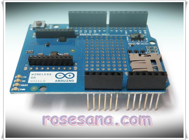
Arduino Wireless SD shield

As the name implies, the Arduino Wireless SD shield serves two functions. Foremost, this shield allows you to easily interface with Xbee transceiver modules to create mesh networks, and other wireless devices. Secondly, the micro SD socket allows you to store and access a large amount of data. Whether using these functions by on their own or together, this chip greatly enhances the capabilities of a standard Arduino.

The Wireless SD shield allows an Arduino board to communicate wirelessly using a wireless module. It is based on the Xbee modules from Digi, but can use any module with the same footprint. The module can communicate up to 100 feet indoors or 300 feet outdoors (with line-of-sight). It can be used as a serial/usb replacement or you can put it into a command mode and configure it for a variety of broadcast and mesh networking options. The shields breaks out each of the Xbee's pins to a through-hole solder pad.

Included on board is a SD card slot. When using the SD Library to access the card, Pin 4 is CS and cannot be used otherwise. SPI also relies on pins 11, 12, and 13 for communication.
An on-board switch allows the wireless module to communicate with the USB-to-serial converter or with the microntroller.

The Arduino Pro

The Arduino Pro is a microcontroller board based on the ATmega168 (datasheet) or ATmega328 (datasheet). The Pro comes in both 3.3V / 8 MHz and 5V / 16 MHz versions. It has 14 digital input/output pins (of which 6 can be used as PWM outputs), 6 analog inputs, a battery power jack, a power switch, a reset button, and holes for mounting a power jack, an ICSP header, and pin headers. A six pin header can be connected to an FTDI cable or Sparkfun breakout board to provide USB power and communication to the board.
The Arduino Pro is intended for semi-permanent installation in objects or exhibitions. The board comes without pre-mounted headers, allowing the use of various types of connectors or direct soldering of wires. The pin layout is compatible with Arduino shields. The 3.3V versions of the Pro can be powered with a battery.
The Arduino Pro was designed and manufactured by SparkFun Electronics.

Summary
  • Microcontroller ATmega168 or ATmega328
  • Operating Voltage 3.3V or 5V
  • Input Voltage 3.35 -12 V (3.3V versions) or 5 - 12 V (5V versions)
  • Digital I/O Pins 14 (of which 6 provide PWM output)
  • Analog Input Pins 6
  • DC Current per I/O Pin 40 mA
  • Flash Memory 16 KB (ATmega168) or 32KB (ATmega328) of which 2 KB used by bootloader
  • SRAM 1 KB (ATmega168) or 2 KB (ATmega328)
  • EEPROM 512 bytes (ATmega168) or 1 KB (ATmega328)
  • Clock Speed 8 MHz (3.3V versions) or 16 MHz (5V versions)
  • Power
  • The Arduino Pro can be powered via the USB header, with a battery, or with an external power supply. The battery power jack is a JST header. A power jack for an external supply can be soldered to the board.

The Arduino Leonardo

The Arduino Leonardo is a microcontroller board based on the ATmega32u4 . It has 20 digital input/output pins (of which 7 can be used as PWM outputs and 12 as analog inputs), a 16 MHz crystal oscillator, a micro USB connection, a power jack, an ICSP header, and a reset button. It contains everything needed to support the microcontroller; simply connect it to a computer with a USB cable or power it with a AC-to-DC adapter or battery to get started.

The Leonardo differs from all preceding boards in that the ATmega32u4 has built-in USB communication, eliminating the need for a secondary processor. This allows the Leonardo to appear to a connected computer as a mouse and keyboard, in addition to a virtual (CDC) serial / COM port. It also has other implications for the behavior of the board; these are detailed on the getting started page.

Summary
  • Microcontroller ATmega32u4
  • Operating Voltage 5V
  • Input Voltage (recommended) 7-12V
  • Input Voltage (limits) 6-20V
  • Digital I/O Pins 20
  • PWM Channels 7
  • Analog Input Channels 12
  • DC Current per I/O Pin 40 mA
  • DC Current for 3.3V Pin 50 mA
  • Flash Memory 32 KB (ATmega32u4) of which 4 KB used by bootloader
  • SRAM 2.5 KB (ATmega32u4)
  • EEPROM 1 KB (ATmega32u4)
  • Clock Speed 16 MHz

Arduino Uno - R3 origin Italy

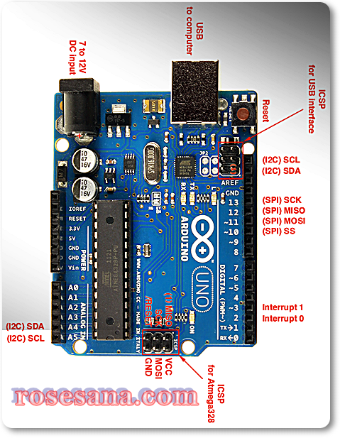
The new Arduino Uno R3. In addition to all the features of the previous board, the Uno now uses an ATmega16U2 instead of the 8U2 found on the Uno (or the FTDI found on previous generations). This allows for faster transfer rates and more memory. No drivers needed for Linux or Mac (inf file for Windows is needed and included in the Arduino IDE), and the ability to have the Uno show up as a keyboard, mouse, joystick, etc.  Online Order

The Uno R3 also adds SDA and SCL pins next to the AREF. In addition, there are two new pins placed near the RESET pin. One is the IOREF that allow the shields to adapt to the voltage provided from the board. The other is a not connected and is reserved for future purposes. The Uno R3 works with all existing shields but can adapt to new shields which use these additional pins.

Arduino is an open-source physical computing platform based on a simple i/o board and a development environment that implements the Processing/Wiring language. Arduino can be used to develop stand-alone interactive objects or can be connected to software on your computer (e.g. Flash, Processing, MaxMSP). The open-source IDE can be downloaded for free (currently for Mac OS X, Windows, and Linux).

Note: The Arduino Uno R3 requires the Arduino 1.0 drivers folder in order to install properly on some computers. We have tested and confirmed that the R3 can be programmed in older versions of the IDE. However, the first time using the R3 on a new computer, you will need to have Arduino 1.0 installed on that machine. If you are interested in reading more about the changes to the IDE, check out the official Arduino 1.0 Release notes!   Onlline Order

Features:
  • ATmega328 microcontroller
  • Input voltage - 7-12V
  • 14 Digital I/O Pins (6 PWM outputs)
  • 6 Analog Inputs
  • 32k Flash Memory
  • 16Mhz Clock Speed

Tuesday, July 24, 2012

MPX5050DP pressure sensor with calibrated and compensated temperature and signal conditioning

MPX5050DP pressure sensor with calibrated compensated temperature and signal conditioning
The MPXx5050 series piezoresistive transducer is a state-of-the-art monolithic silicon pressure sensor designed for a wide range of applications, but particularly those employing a microcontroller or microprocessor with A/D inputs. This patented, single element transducer combines advanced micromachining techniques, thin-film metallization, and bipolar processing to provide an accurate, high level analog output signal that is proportional to the applied pressure.

Features
• 0.2 to 4.7 V Output
• 0 to 50 kPa (0 to 7.25 psi)
• 2.5% Maximum Error over 0° to 85°C
• Ideally suited for Microprocessor or Microcontroller-Based Systems
• Temperature Compensated Over -40° to +125°C
• Patented Silicon Shear Stress Strain Gauge
• Durable Epoxy Unibody Element
• Easy-to-Use Chip Carrier Option

MPX2100DP pressure sensor by Freescale Semiconductor

100 kPa On-Chip Temperature Compensated and Calibrated Silicon Pressure Sensors
The MPX2100 series devices silicon piezoresistive pressure sensors providing a highly accurate and linear voltage output directly proportional to the applied pressure. The sensor is a single, monolithic silicon diaphragm with the strain gauge and a thin-film resistor network integrated on-chip. The chip is laser trimmed for precise span and offset calibration an temperature compensation.

Features
  • Temperature Compensated Over 0°C to +85°C
  • Available in Absolute, Differential and Gauge Configurations
  • Easy to Use Chip Carrier Package Options
  • Ratiometric to Supply Voltage
  • ±0.25% Linearity (MPX2100D Series)
  • 0 to 100 kPa (0 to 14.5 psi)
  • 40 mV Full Scale Span (Typical)


Application Examples
  • Pump/Motor Controllers
  • Robotics
  • Level Indicators
  • Medical Diagnostics
  • Pressure Switching
  • Barometers

Monday, July 23, 2012

Go!Link with Logger Lite software bundle

Various types of sensor interface module of Vernier Software  Logger Lite


specifications:
- Consisting of Go! Link (H / W) and Logger Lite Software
- Compatible with a variety of Vernier sensors are berkonektor BTA
- Interface Go! Link: USB
- Has features to predict the outcome of the measurement prior to actual measurements
- The sensor reading is represented in the form of graphics and animation
- Compatible with OS XP ​​(32-bit), Vista (32-64 bit), Win7 (32-64bit), Mac OS X (10.4, 10.5, 10.6)

Friday, July 20, 2012

DFRduino Mega 1280 (Arduino Mega 1280 Compatible)

The DFRobot DFRduino ATMega1280 MEGA USB Microcontroller is a microcontroller board based on the ATmega1280 integrated circuit. It 00% same as the original Arduino Mega.It has 54 digital input/output pins (of which 14 can be used as PWM outputs), 16 analog inputs, 4 UARTs (hardware serial ports), a 16 MHz crystal oscillator, a USB connection, a power jack, an ICSP header and a reset button. It contains everything needed to support the microcontroller; simply connect it to a computer with a USB cable or power it with an AC-to-DC adapter or battery to get started. The Mega is compatible with most shields designed for the Arduino Duemilanove or Diecimila. The DFRobot ATMega1280 MEGA USB Microcontroller can be powered via the USB connection or with an external power supply. The power source is selected automatically. External (non-USB) power can come either from an AC-to-DC adapter (wall-wart) or battery. The adapter can be connected by plugging a 2.1mm center-positive plug into the board's power jack. Leads from a battery can be inserted in the Gnd and Vin pin headers of the POWER connector. This board is almost identical to the Arduino MEGA with the exception of the color of the PCB.

Specifications
  • Microcontroller ATmega1280
  • Operating Voltage 5V
  • Input Voltage (recommended) 7-12V
  • Input Voltage (limits) 6-20V
  • Digital I/O Pins 54 (of which 14 provide PWM output)
  • Analog Input Pins 16
  • DC Current per I/O Pin 40 mA
  • DC Current for 3.3V Pin 50 mA
  • Flash Memory 128 KB of which 4 KB used by bootloader
  • SRAM 8 KB
  • EEPROM 4 KB
  • Clock Speed 16 MHz


Shield Compatibility

The Mega is designed to be compatible with most shields designed for the Diecimila or Duemilanove. Digital pins 0 to 13 (and the adjacent AREF and GND pins), analog inputs 0 to 5, the power header, and ICSP header are all in equivalent locations. Further the main UART (serial port) is located on the same pins (0 and 1), as are external interrupts 0 and 1 (pins 2 and 3 respectively). SPI is available through the ICSP header on both the Mega and Duemilanove / Diecimila. Please note that I2C is not located on the same pins on the Mega (20 and 21) as the Duemilanove / Diecimila (analog inputs 4 and 5).

The Mega is compatible with
  • Arduino Mega Prototype Shield
  • Arduino I/O Shield
  • Arduino LCD Shield
  • Arduino Motor Shield

The Mega is NOT compatible with 'Arduino Ethernet Shield'

Thursday, July 19, 2012

PANASONIC EW - AMN12111 - SENSOR, PIR, COMPACT, 2M, BLACK

PANASONIC EW - AMN12111 - SENSOR, PIR, COMPACT, 2M, BLACK Passive infrared motion sensor.


specifications:
- Detection distance of 2 meters.
- Slight motion detection.
- Digital Output, High / Low.
- 12.7 x 15.2 mm, the smallest in the world.
- The angle of view of 91A º (V & H).
- 5 volt power supply.
- Color black lenses.
- SVHC: No SVHC (19-Dec-2011)
- Body Colour: Black
- Operating Temperature Max: 60°C
- Operating Temperature Min: -20°C
- Output Current: 100µA
- Sensing Range: 2m 91° Horizontal, 91° Vertical
- Series: MP
- Supply Voltage Max: 6VDC
- Supply Voltage Min: 3VDC

Eltec 442-3 Pyroelectric Detector

The 442-3 IR-EYE™ Integrated Sensor is a Lithium Tantalate pyroelectric, parallel opposed, dual element, high gain detector with integral analog signal processing. This high gain detector offers great detection capability over a temperature range of -40 to +70 ºC. This detector has short circuit protection but DOES NOT protect against reverse supply polarity.

Eltec 442-3 Near-infrared Pyroelectric detector. Used to sense body heat or flames. Comes with 1-inch diameter Fresnel lens. Analog output pin provides information about direction of motion of heat source.
Extremely simple to use, this sensor requires no external components, only power and ground connections. The output is an analog signal (0-5V) which can be read by any microcontroller with a spare analog input pin.
  • Eliminate Burn-In Tests
  • Improve RF Immunity
  • Eliminate False Alarms
  • Miniaturize Circuitry
  • Reduce Components
  • Reduce Repairs


ATMega1280 risc microcontroller

The ATMEGA1280 high-performance, low-power Atmel 8-bit AVR RISC-based microcontroller combines 128KB ISP flash memory, 8KB SRAM, 4KB EEPROM, 86 general purpose I/O lines, 32 general purpose working registers, real time counter, six flexible timer/counters with compare modes, PWM, 4 USARTs, byte oriented 2-wire serial interface, 16-channel 10-bit A/D converter, and a JTAG interface for on-chip debugging. The device achieves a throughput of 16 MIPS at 16 MHz and operates between 2.7-5.5 volts.
By executing powerful instructions in a single clock cycle, the device achieves a throughput approaching 1 MIPS per MHz, balancing power consumption and processing speed.

Key parameters for ATmega1280
  • Parameter :Value
  • Flash (Kbytes): 128 Kbytes
  • Pin Count: 100
  • Max. Operating Frequency:16 MHz
  • CPU: 8-bit AVR
  • # of Touch Channels:16
  • Hardware QTouch Acquisition:No
  • Max I/O Pins:86
  • Ext Interrupts:32
  • USB Speed:No
  • USB Interface:No
  • SPI:5
  • TWI (I2C):1
  • UART:4
  • Graphic LCD:No
  • Video Decoder:No
  • Camera Interface:No
  • ADC channels:16
  • ADC Resolution (bits):10
  • ADC Speed (ksps):15
  • Analog Comparators:1
  • Resistive Touch Screen:No
  • DAC Resolution (bits):0
  • Temp. Sensor:No
  • Crypto Engine:No
  • SRAM (Kbytes):8
  • EEPROM (Bytes):4096
  • Self Program Memory:YES
  • External Bus Interface:0
  • DRAM Memory:No
  • NAND Interface:No
  • picoPower:No
  • Temp. Range (deg C):-40 to 85
  • I/O Supply Class:1.8 to 5.5
  • Operating Voltage (Vcc):1.8 to 5.5
  • FPU:No
  • MPU / MMU:no / no
  • Timers:6
  • Output Compare channels:16
  • Input Capture Channels:4
  • PWM Channels:15
  • 32kHz RTC:Yes
  • Calibrated RC Oscillator:Yes

Honeywell advanced Hall Open-loop Current Sensor

This is an advanced Hall effect-based open-loop current sensor made by Honeywell. It could measure DC, AC or pulsating current. Users can run the cable directly through the opening (10.4mm × 20.4mm) of the current sensor without worrying about burning-up or inaccuracy because the current sensor consumes low power and there is almost no insertion loss.


Features

  • Wired open-loop design with multiple turns for increased sensitivity
  • ac or dc current sensing
  • Linear ratiometric output
  • Current sinking or sourcing output for interfacing flexibility
  • Low insertion loss
  • Fast response time
  • Compact size for applications with limited space
  • Accurate, low-cost sensing
  • Minimum energy dissipation
  • Maximum current limited only by conductor size
  • Built-in temperature compensation promotes reliable operation
  • Operating temperature range -25 �C to 100 �C [-13 �F to 212 �F]
  • RoHs compliant (lead-free)


Typical Applications

  • Motor control in applications, HVAC and consumer tools
  • Current monitoring of electronic circuits
  • Overcurrent protection
  • Ground fault detectors
  • Robotics
  • Industrial process control
  • UPS and telecommunication power supplies
  • Welding current monitoring
  • Battery management systems in mobile equipment
  • Watt meters
  • Variable speed drives

MAX195 16-Bit, 85ksps ADC with 10µA Shutdown

The MAX195 is a 16-bit successive-approximation analog-to-digital converter (ADC) that combines high speed, high accuracy, low power consumption, and a 10µA shutdown mode. Internal calibration circuitry corrects linearity and offset errors to maintain the full rated performance over the operating temperature range without external adjustments. The capacitive-DAC architecture provides an inherent 85ksps track/hold function.

The MAX195, with an external reference (up to +5V), offers a unipolar (0V to VREF) or bipolar (-VREF to VREF) pin-selectable input range. Separate analog and digital supplies minimize digital-noise coupling.

The chip select (CS) input controls the three-state serial-data output. The output can be read either during conversion as the bits are determined, or following conversion at up to 5Mbps using the serial clock (SCLK). The end-of-conversion (EOC) output can be used to interrupt a processor, or can be connected directly to the convert input (CONV) for continuous, full-speed conversions.

The MAX195 is available in 16-pin DIP, wide SO, and ceramic sidebraze packages.

Key Features
  • 16 Bits, No Missing Codes
  • 90dB SINAD
  • 9.4µs Conversion Time
  • 10µA (max) Shutdown Mode
  • Built-In Track/Hold
  • AC and DC Specified
  • Unipolar (0V to VREF) and Bipolar (-VREF to VREF) Input Range
  • Three-State Serial-Data Output
  • Small 16-Pin DIP, SO, and Ceramic SB Packages

Applications/Uses
  • Audio
  • Digital Signal Processing (DSP)
  • Industrial Controls
  • Medical Signal Acquisition
  • Multiple Transducer Measurements
  • Portable Instrumentation
  • Robotics

Vibration Analysis

Wednesday, July 18, 2012

Meanwell SE-600-24 , 600 Watt single output (24VDC) Switching power supply

Meanwell Single output power supply SE-600 series (SE-600-24) 


Features:

  • AC input active surge current limiting
  • AC input range selected by switch 90-132VAC or 180-264VAC
  • Protection: Short circuit / overload / over voltage / over temperature (85 deg C)
  • Forced air cooling by built in DC fan
  • high power density 4.9watt/inch3
  • built in remote sense function
  • UL Approved
  • 24VDC output/0-25 Amp / 600 Watt 
  • voltage adjust range: 22-26.4VDC 
  • dimension 247*127*63.5mm
  • weight 2.1Kg

VDIP2 VINC1L Module-based USB controller chip from FTDI Vinculum chip VNC1A

The VDIP2 module is an MCU to embedded USB host controller development module for the VNC1L I.C. 
device.The VDIP2 is supplied on a PCB designed to fit into a 40 pin DIP socket, and provides access to the UART, parallel FIFO, and SPI interface pins on the VNC1L device, via its AD and AC bus pins. All other Vinculum I/O pins are also accessable. Not only is it ideal for developing and rapid prototyping of VNC1L designs, but also an attractive quantity discount structure makes this module suitable for incorporation into low and medium volume finished product designs.

The Vinculum VNC1L is the first of FTDI’s Vinculum family of Embedded USB host controller integrated circuit devices. Not only is it able to handle the USB Host Interface, and data transfer functions but owing to the inbuilt MCU and embedded Flash memory, Vinculum can encapsulate the USB device classes as well. When interfacing to mass storage devices such as USB Flash drives, Vinculum also transparently handles the FAT File structure communicating via UART, SPI or parallel FIFO interfaces via a simple to implement command set. Vinculum provides a new cost effective solution for providing USB Host capability into products that previously did not have the hardware resources available. The VNC1L is available in Pb-free (RoHS compliant) compact 48-Lead LQFP package. 


specifications:
- Single 5V Supply Voltage
- Equipped with LED indicators for power and data
- There are 2 pieces USB socket "A" to the vertical position as the interface with USB devices
- There is a jumper for selection interface UART, parallel FIFO, or SPI
- Available 3.3V power supply lines / 200mA for external circuit
- Update the firmware can be done via USB Flash disk or UART interface
- VNC1L firmware programming control pins PROG # and RESET # Brought out onto jumper interface
- Pb-free and RoHS compilant
- Modules are supplied with a firmware VDIP2 Vinculum VDAP in the sales package

MPX5100GP Pressure sensor with temperature compensation, signal conditioning, and has been calibrated.

The MPX5100 series piezoresistive transducer is a state-of-the-art monolithic silicon pressure sensor designed for a wide range of applications, but particularly those employing a microcontroller or microprocessor with A/D inputs. This patented, single element transducer combines advanced micromachining techniques, thin-film metallization, and bipolar processing to provide an accurate, high level analog output signal that is proportional to the applied pressure.

Features
• 2.5% Maximum Error over 0° to 85°C
• Ideally suited for Microprocessor or Microcontroller-Based Systems
• Patented Silicon Shear Stress Strain Gauge
• Available in Absolute, Differential and Gauge Configuration
• Durable Epoxy Unibody Element
• Easy-to-Use Chip Carrier Option
• 0 to 14.5 psi / 0.2 to 4.7 V Output

Typical Applications
• Patient Monitoring
• Process Control
• Pump/Motor Control
• Pressure Switching

Tuesday, July 17, 2012

The STM32F103RET6 microcontroller

The STM32F103RET6 microcontroller has 512 KB of Flash, 64 KB RAM, 3x16-channel 12-bit A/D converter, 6x16-bit (IC/OC/PWM) timer, 3xSPI, 2I2S, 2xI2C, 5USART, SDIO, USB, CAN, 51 I/Os in a 64-Pin 10 mm x 10 mm x 1.4 mm LQFP package.

The STM32F103xC, STM32F103xD and STM32F103xE performance line family incorporates the high-performance ARM®Cortex™-M3 32-bit RISC core operating at a 72 MHz frequency, high-speed embedded memories (Flash memory up to 512 Kbytes and SRAM up to 64 Kbytes), and an extensive range of enhanced I/Os and peripherals connected to two APB buses. All devices offer three 12-bit ADCs, four general-purpose 16-bit timers plus two PWM timers, as well as standard and advanced communication interfaces: up to two I2Cs, three SPIs, two I2Ss, one SDIO, five USARTs, an USB and a CAN.

The STM32F103xx high-density performance line family operates in the –40 to +105 °C temperature range, from a 2.0 to 3.6 V power supply. A comprehensive set of power-saving mode allows the design of low-power applications.

Features:
  • Core: ARM 32-bit Cortex™-M3 CPU
  • 72 MHz maximum frequency, 1.25 DMIPS/MHz (Dhrystone 2.1) performance at 0 wait state memory access
  • Single-cycle multiplication and hardware division
  • Memories
  • 256 to 512 Kbytes of Flash memory
  • up to 64 Kbytes of SRAM
  • Flexible static memory controller with 4 Chip Select. Supports Compact Flash, SRAM, PSRAM, NOR and NAND memories
  • LCD parallel interface, 8080/6800 modes
  • Clock, reset and supply management
  • 2.0 to 3.6 V application supply and I/Os
  • POR, PDR, and programmable voltage detector (PVD)
  • 4-to-16 MHz crystal oscillator
  • Internal 8 MHz factory-trimmed RC
  • Internal 40 kHz RC with calibration
  • 32 kHz oscillator for RTC with calibration
  • Low power
  • Sleep, Stop and Standby modes
  • VBAT supply for RTC and backup registers
  • 3 × 12-bit, 1 μs A/D converters (up to 21 channels)
  • Conversion range: 0 to 3.6 V
  • Triple-sample and hold capability
  • Temperature sensor
  • 2 × 12-bit D/A converters
  • DMA: 12-channel DMA controller
  • Supported peripherals: timers, ADCs, DAC, SDIO, I2Ss, SPIs, I2Cs and USARTs
  • Debug mode
  • Serial wire debug (SWD) & JTAG interfaces
  • Cortex-M3 Embedded Trace Macrocell™
  • Up to 112 fast I/O ports
  • 51/80/112 I/Os, all mappable on 16 external interrupt vectors and almost all 5 V-tolerant
  • Up to 11 timers
  • Up to four 16-bit timers, each with up to 4 IC/OC/PWM or pulse counter and quadrature (incremental)
  • ncoder input
  • 2 × 16-bit motor control PWM timers with dead-time generation and emergency stop
  • 2 × watchdog timers (Independent and Window)
  • SysTick timer: a 24-bit downcounter
  • 2 × 16-bit basic timers to drive the DAC
  • Up to 13 communication interfaces
  • Up to 2 × I2C interfaces (SMBus/PMBus)
  • Up to 5 USARTs (ISO 7816 interface, LIN, IrDA capability, modem control)
  • Up to 3 SPIs (18 Mbit/s), 2 with I2S interface multiplexed
  • CAN interface (2.0B Active)
  • USB 2.0 full speed interface
  • SDIO interface
  • CRC calculation unit, 96-bit unique ID
  • ECOPACK®packages


Applications:
  • Motor drive
  • Application control
  • Medical and handheld equipment
  • PC and gaming peripherals
  • GPS platforms
  • Industrial applications
  • PLCs
  • Inverters
  • Printers
  • Scanners
  • Alarm systems
  • Video intercoms
  • HVACs

LPC1769FBD100,551 chip

LPC1769FBD100,551 Cortex-M3 with 512 kB flash, 64 kB SRAM, Ethernet, USB 2.0 Device/Host/OTG, 12-bit ADC, DAC, I2S

The LPC1769 is a Cortex-M3 microcontroller for embedded applications featuring a high level of integration and low power consumption at frequencies of 120 MHz. Features include 512 kB of flash memory, 64 kB of data memory, Ethernet MAC, USB Device/Host/OTG, 8-channel DMA controller, 4 UARTs, 2 CAN channels, 3 SSP/SPI, 3 I2C, I2S, 8-channel 12-bit ADC, 10-bit DAC, motor control PWM, Quadrature Encoder interface, 4 general purpose timers, 6-output general purpose PWM, ultra-low power Real-Time Clock with separate battery supply, and up to 70 general purpose I/O pins. The LPC1769 is pin-compatible to the 100-pin LPC2368 ARM7 MCU


Features and benefits

  • ARM Cortex-M3 processor, running at frequencies of up to 120 MHz
  • ARM Cortex-M3 built-in Nested Vectored Interrupt Controller (NVIC)
  • Up to 512 kB on-chip flash programming memory
  • Up to 64 kB On-chip SRAM
  • In-System Programming (ISP) and In-Application Programming (IAP)
  • Eight channel General Purpose DMA controller (GPDMA)
  • Ethernet MAC with RMII interface and dedicated DMA controller
  • USB 2.0 full-speed device/Host/OTG controller
  • Four UARTs with fractional baud rate generation, internal FIFO, and DMA support
  • CAN 2.0B controller with two channels
  • SPI controller with synchronous, serial, full duplex communication
  • Two SSP controllers with FIFO and multi-protocol capabilities
  • Three enhanced I2C bus interfaces
  • I2S (Inter-IC Sound) interface
  • 70 General Purpose I/O (GPIO) pins with configurable pull-up/down resistors
  • 12-bit/8-ch Analog/Digital Converter (ADC) with conversion rates up to 200 kHz
  • 10-bit Digital/Analog Converter (DAC) with dedicated conversion timer and DMA
  • Four general purpose timers/counters
  • One motor control PWM with support for three-phase motor control
  • Quadrature encoder interface that can monitor one external quadrature encoder
  • One standard PWM/timer block with external count input
  • Low power RTC with a separate power domain and dedicated oscillator
  • WatchDog Timer (WDT)
  • ARM Cortex-M3 system tick timer, including an external clock input option
  • Repetitive interrupt timer provides programmable and repeating timed interrupts
  • Each peripheral has its own clock divider for further power savings
  • Standard JTAG test/debug interface for compatibility with existing tools
  • Integrated PMU (Power Management Unit)
  • Four reduced power modes: Sleep, Deep-sleep, Power-down, and Deep power-down
  • Single 3.3 V power supply (2.4 V to 3.6 V)
  • Four external interrupt inputs configurable as edge/level sensitive
  • Non-maskable Interrupt (NMI) input
  • Wake-up Interrupt Controller (WIC)
  • Processor wake-up from Power-down mode via any interrupt
  • Brownout detect with separate threshold for interrupt and forced reset
  • Power-On Reset (POR)
  • Crystal oscillator with an operating range of 1 MHz to 25 MHz
  • 4 MHz internal RC oscillator trimmed to 1 % accuracy
  • Code Read Protection (CRP) with different security levels
  • Unique device serial number for identification purposes


Applications

  • eMetering
  • Lighting
  • Industrial networking
  • Alarm systems
  • White goods
  • Motor control

GWS S35/STD/F 360 Degree servo

GWS S35/STD/F 360 Degree servo
Servo motors continuous type product of GWS.


specifications:
- Type of round: Continuous (360Â °)
- Type of control: PWM
- Working Voltage: 4.8 - 6.0 V
- Current consumption: 0.3 A @ Full Speed ​​& No Load
- Maximum Torque: 2.8 kg / cm @ 6.0 V
- Rotational speed Maximum: 0:13 sec / 6.0 V @ 60A °
- Dimensions: 39.5 x 20.0 x 39.5 mm
- Weight: 42 g

GWS S04/BB/F servo

GWS S04/BB/F servo, Heavy duty type servo GWS standard production

- Supply voltage 4.8-6.0V
- Speed ​​sec/60 degrees @ 6V 0:20
- Torque 13 kg / cm (181 oz / in) @ 6V
- Weight 110 g (3.88 oz)
- Size 54.4x 26.5x 51.5 mm / inch 2:03 2.14x 1.04x

LPC1769 LPCXpresso Board

The LPC1769 LPCXpresso board with NXP's ARM Cortex-M3 microcontroller has been designed to make it as easy as possible to get started with Cortex-M3. The LPCXpresso comprises a target board combined with a JTAG debugger. A free Eclipse-based IDE from Code Red is also included.

The LPC1769 has 64 kB SRAM, 512 kB Flash, 4xUART, 3xI2C, SPI, 2xSSP, 2xCAN, PWM, USB 2.0 Device/Host/OTG, RTC, Ethernet, I2S, etc. Embedded Artists also provides a Prototype board and a Base board that makes it possible to make experiments and prototyping with many peripherals.

specs:


ProcessorNXP's Cortex-M3 LPC1769 microcontroller in LQFP100 package
Flash512 kB
Data Memory64 kB
Clock Crystals12.000 MHz crystal for CPU
Dimensions35 x 140 mm
Power3.15V-3.3V external powering, or
from USB via JTAG probe (LPC-LINK)
ConnectorsAll relevant LPC1769 pins available on expansion connector (2x27 pin rows, 100 mil pitch, 900 mil between rows)
Other• Embedded JTAG (LPC-LINK) functionality via LPCXpresso toolchain
• LPC-LINK can be connected to external target processor after modifications to the LPCXpresso board
• LED on PIO0_22

STM32VLDISCOVERYDiscovery kit for the Value line STM32F100

The STM32VLDISCOVERY is a low-cost and quick way to discover the STM32 value line. It includes everything required for beginners and experienced users to get started quickly. The STM32 value line Discovery includes an STM32F100 value line microcontroller in a 64-pin LQFP and an incircuit ST-Link debugger / programmer to debug Discovery applications and other target board applications. A large number of free ready-to-run application firmware examples are available on www.st.com/stm32-discovery to support quick evaluation and development using the LEDs, button and extension header for connection to other boards or devices.

Key Features

  • STM32F100RB microcontroller, 128 KB Flash, 8 KB RAM in 64-pin LQFP
  • On-board ST-Link with selection mode switch to use the kit as a stand-alone ST-Link (with SWD connector)
  • Designed to be powered by USB or an external supply of 5 V or 3.3 V
  • Can supply target application with 5 V and 3 V
  • Two user LEDs (green and blue)
  • One user push button
  • Extension header for all QFP64 I/Os for quick connection to prototyping board or easy probing
Summary:
STM32 microcontroller development board module Value Line ARM Cortex-M3 ST Microelectronics original of the completed On-board ST-Link as a programmer and debugger with USB interface.

GWS PICO+ F/BB/F standard servo

GWS PICO+ F/BB/F standard servo
standard type servo motors GWS

specifications:
- Supply voltage 4.8 - 6.0V
- Size 22.8x 9.5x 19.8
- Weight 6.2gram
- Speed ​​0.12 sec/60 derajat@4.8V
- @ 4.8V Torque 0.78kg/cm


GWS NARO PRO /STD/F

GWS NARO PRO /STD/F standard type servo motors GWS.

specifications:
- Type of round: Standard (180Â °)
- Type of control: PWM
- The working voltage: 4.8 V
- Current consumption: -
- Maximum Torque: 1.6 kg / cm @ 4.8V
- The maximum rotary speed: 0.12 sec / 4.8 V @ 60A °
- Dimensions: 27 x 12.7 mm x 22:45
- Weight: 13 g

GWS MICRO/2BBMG servo

The GWS Micro 2BBMG servo motor is less than half the size of a standard-sized servo motor, yet packs an amazing 6.4kg-cm of torque! It features metal gears and a dual ball bearings system for virtually indestructable performance. It's compatible with motors from Futaba, JR, Hitec, Airtronics (Sanwa), Multiplex and other popular servo brands. This servo motor comes with various horns for attachment.

Servo motors are extremely useful in robotics and come in various shapes and sizes. They have built in control circuitry to allow the user to precisely control the position of the motor shaft. Compared to DC motors, servo motors are very powerful for their size.

specifications:
- Type of round: Standard (180Â °)
- Type of control: PWM
- Working Voltage: 4.8 - 6.0 V
- Current consumption: -
- Maximum Torque: 5.4 kg / cm @ 4.8V
- Rotational speed Maximum: 0:17 sec / ° @ 4.8V 60A
- Dimensions: 28.0 x 14.0 x 29.8 mm
- Weight: 28 g
Note: The 2BBMG designation stands for 2 Ball Bearings + Metal Gears

MSC1211Y4PAGT chip

MSC1211Y4PAGT is 8051 family microcontroller with ADC & DAC precision-made Texas Instruments.

specifications:
- Features analog:
· 24-bits resolution.
· Programmable gain amplifier (1-128).
· On-chip voltage reference (accuracy = 0.2%, drift = 5ppm / C).
· 8 differential / single-ended channels.
· On-chip offset / gain calibration and temperature sensor.
· Selectable input buffer, burnout detect.
· 4 16-bit DAC Voltage (settling time = 8us).
- 16 MB Flash Data memory / w security.
- Flash memory partitioning.
- In-system programmable serially.
- 2 MB boot ROM.
- 1280 bytes of data SRAM.
- Dual Data pointer, additional 32-bit accumulator.
- The frequency of the oscillator max 30 MHz, 4 clock per instruction cycle.
- 34 pin I / O, three 16-bit timer / counter, 16-bit PWM.
- System timer, programmable watchdog timer.
- Full duplex dual UART, master / slave SPI / w DMA, multi-master I2C.
- Power management control, internal clock divider, idle and stop modes.
- Programmable brownout reset and low voltage detector.
- 21 interrupt sources, 6 external interrupt, two hardware breakpoint.
- Power supply: +2.7 - +5.25 VDC.
- Package: TQFP-64.

Monday, July 16, 2012

GWS Servo S03T/STD/F

GWS Servo S03T/STD/F
standard type servo motors by GWS

Specs:
- Supply voltage 4.8-6.0V
- Speed ​​sec/60 degrees @ 6V 0:22
- Torque 6.5 kg / cm @ 6V
- Weight 46 g
- Size 39.5x 20.0x 39.5 mm

GWS Servo S125-1T/2BB/F (Futaba)

GWS Servo S125-1T/2BB/F (Futaba)
■ The RC servo (Taiwan) GWS.
■ GWS125-1T/2BB/FUTABA
■  type torque (360-degree rotation) rotation 1: 6.6kg (4.8V) 7.6kg (6V)
■ Weight: 50g
■ Speed: 1.56 seconds degrees / 360 (4.8V)
■ Size: 5cm: 40.5x20x42mm pulley diameter
※ terminal sequence is a Futaba type., Type control: PWM

GWS NARO PRO D. BB/MG/F

GWS NARO PRO D. BB/MG/F
Standard Digital Servo Motor type is equipped with ball bearings


specifications:
- Torque: 2kg-cm @ 6VDC
- Speed: 0.09 s/60 °
- Dimensions: 27 x 12.7 x 24.65 mm

GWS S15CLN/2BBMG/F standard servo

GWS S15CLN/2BBMG/F  core-less standard type servo motors are equipped with 2 GWS Ball Bearings and Metal Gear.

specifications:
- Type of round: Standard (180 deg)
- Type of control: PWM
- Working Voltage: 4.8 - 6.0 V
- Maximum torque: 9.2 @ 6.0 V kg.cm
- Rotational speed Maximum: 0:13 sec / 50 deg@6.0 V
- Dimensions: 40.5 x 20 x 37.5 mm
- Weight: 66.4 g

GWS NARO Super Servo Digital BB/MG/F

GWS Naro BB/MG/F
Digital Servo motors are equipped with a standard type of ball bearings as well as Metal Gear.


specifications:
- Type of round: Standard (180 deg)
- Type of control: PWM
- Working Voltage: 4.8 - 6.0 V
- Current consumption: -
- Maximum torque: 5.0 kg.cm @ 6.0 V
- The maximum rotary speed: 0.08 sec / 60 deg
- Dimensions: 27 x 12.7 x 26.65 mm
- Weight: 19 g

GWS S03N/2BB/F standard servo

The GWS S03N/2BB/F standard type servo motors GWS with 2 Ball Bearings.

specifications:
- Type of round: Standard (180Â °)
- Type of control: PWM
- Working Voltage: 4.8 - 6.0 V
- Current consumption: -
- Maximum Torque: 3.2 kg / cm @ 6.0 V
- The maximum rotary speed: 0.15 sec / 6.0 V @ 60A °
- Dimensions: 39.5 x 20.0 x 35.6 mm
- Weight: 41 g

GWS S777CG/6BB/F heavy duty servo

GWS S777CG/6BB/F heavy duty servo
Heavy dutty production standard GWS servo is equipped with 6 Ball Bearing.


specifications:
- Type of round: Standard (180Â °)
- Type of control: PWM
- The working voltage: 4.8 â € "6.0 VDC
- Current consumption: -
- Maximum torque: 6.0 VDC @ 42 kg.cm
- The maximum rotary speed: 0.12 sec / 6.0 VDC @ 60A °
- Dimensions: 65.0 x 32.0 x 70.4 mm
- Weight: 190 g

The GWS Mini Servo F/BB

The GWS Mini Servo is slightly smaller and lighter than a standard servo, but it delivers the performance of a standard servo. It is recommended for smaller robots, or in projects where space is tight. Servos may be controlled directly from a BASIC Stamp I/O pin by using the PULSOUT command. Two mini servos are used tho make the Parallax Toddler Robot walk. Size: 35.0 mm x 16.9 mm x 32.0 mm.

specifications:
- Torque: 39 oz-in @ 4.8 V or 47 oz-in @ 6.0 V.
- Speed​​: 0.15 sec/60deg @ 4.8 V or 6.0 V. 0.12 @ sec/60deg
- Dimensions: 1.38 x 0.67 x 1.26 ins.
- Weight: 0.94 oz

GWS S03T/HT/BB

GWS S03T/HT/BB
Standard type servo motors GWS production that has great torque and features 2 ball bearings.

specifications:
- Torque: 7.2 kg.cm @ 4.8 V.
- Speed​​: 0.33 sec/60 ° @ 4.8 V.
- Dimensions: 1.56 x 0.79 x 1.56 ins.
- Weight: 46gram

The Arduino Fio

The Arduino Fio is a microcontroller board based on the ATmega328P (datasheet) runs at 3.3V and 8 MHz. It has 14 digital input/output pins (of which 6 can be used as PWM outputs), 8 analog inputs, an on-board resonator, a reset button, and holes for mounting pin headers. It has connections for a Lithium Polymer battery and includes a charge circuit over USB. An XBee socket is available on the bottom of the board.

The Arduino Fio is intended for wireless applications. The user can upload sketches with an a FTDI cable or Sparkfun breakout board. Additionally, by using a modified USB-to-XBee adaptor such as XBee Explorer USB, the user can upload sketches wirelessly. The board comes without pre-mounted headers, allowing the use of various types of connectors or direct soldering of wires.

The Arduino Fio was designed by Shigeru Kobayashi and SparkFun Electronics, and manufactured by SparkFun Electronics.

Summary

  • Microcontroller ATmega328P
  • Operating Voltage 3.3V
  • Input Voltage 3.35 -12 V
  • Input Voltage for Charge 3.7 - 7 V
  • Digital I/O Pins 14 (of which 6 provide PWM output)
  • Analog Input Pins 8
  • DC Current per I/O Pin 40 mA
  • Flash Memory 32 KB (of which 2 KB used by bootloader)
  • SRAM 2 KB
  • EEPROM 1 KB
  • Clock Speed 8 MHz

Sunday, July 15, 2012

CM02/400 - Radio Communications Module

The CM02 module, together with its companion RF04 module, form a complete interface between your PC and our range of I2C modules. You can send commands down to your robot and receive telemetry data back up to the PC. Now you have all the modules necessary to control your robot from your PC. The CM02 is powered from your robots battery, which can be anything from 6v to 12v. The CM02 can monitor battery voltage and report this back to the PC (so your robot knows when its hungry!). There are four I2C connectors on the CM02, but your not limited to four I2C devices. In practice, you may only need one connector and route the I2C bus around all the modules you wish. Bit rate on the I2C bus is approximately 100KHz.

specifications:
- Catudaya 6VDC - 12VDC
- Based ER400TRS and PIC16F88
- The working frequency: 433MHz
- Transmit Power 10mW
- Data transfer: 19.2 Kbps
- Range: 250m (LOS)
- Can send and retrieve data from another device through the international antamuka IC2, such as: SRF08
- Interface: I2C