Wednesday, September 22, 2010

B Cam-21 , Color Camera Module

B Cam-21 , Color Camera Module.
by Comedia Ltd.
  • Small size
  • low cost
  • 12V operation
  • Low power consumption
  • Direct connect to standard video monitor 
  • Color
  • 1/3"Lens Format
  • OV7910 Imager
  • Lens: f6.0mm, F1.8

EVU20 , USB2.0 EV Board for Camera Module

EVU20 , USB2.0 EV Board for Camera Module by COMedia Ltd.

THE EVU20 is the USB 2.0 evaluation board for digital camera module from COMedia Ltd. It provides a high speed USB interface to upload video data from camera module to PC. The EV board is specially designed for evaluating the digital camera module using OmniVision image sensor.

Features
  • USB2.0 standard compliance
  • Transfer speed upto 480Mbps
  • Support Win2K /XP
  • Evaluate sensor from 1.3 to 5 Meg Pixel
  • Small board size (61 x 41 mm)
  • No external power is required
  • Support different sensor module
  • Still picture capture by hardware snap shot
  • Auto launch

Associated Camera Module

Model Sensor Resolution
AA2640 OV2640 1600x1200
AA9653 OV9653 1280x1024
AA10620 OV10620 768x506

AA5620 Camera Module

* Small size
AA5620 Camera Module
* low cost
* Low power consumption
* 16x2pin 0.1" pitch connector
* Serial camera control bus interface

Resolution: QSXGA 5.17M
Pixels: 2592 x 1944
Lens Format: 1/1.8"
Imager: OV5620
Lens: f8.2mm, F2.8
Module Size: 41x34 mm

the controller for this camera module sold separately.

Monday, September 20, 2010

CMU CAM2 with OV7620

CMU CAM2 with OV7620 Hardware Overview
There are two main hardware differences which are important, the CMUcam2 uses a different processor than the CMUcam1 and the CMUcam2 incorporates a frame buffer chip which the CMUcam1 does not.
The CMUcam2 uses the SX52 processor and the CMUcam1 uses the SX28 processor, both from in the SX processor series from Ubicom. In both cases the processor runs at 75 Mhz so there is no difference in processor speed or computational power. The advantages of the new processor are that it has more RAM (262 vs. 136 bytes), more ROM (4096 vs. 2048 words), and more I/O pins. More RAM and ROM meant we could write more code and more complex code which allowed us to incorporate more functionality in the CMUcam2. The larger number of I/O pins meant that we had more pins left over for other functions - like more servos, more configuration jumpers, etc.
The big difference between the two systems is that the CMUcam2 includes the AL422B frame buffer chip from Averlogic where the CMUcam1 does not. This allows the CMUcam2 hardware to quickly capture a single complete frame and store it the frame buffer memory. This has a number of advantages:
  • More Complex Processing. In the CMUcam1 the processor had to process the pixel data stream on the fly as it was output by the camera module. This design helped reduce the complexity and cost of the system hardware. However, it limited the complexity of the processing because it had to be performed in real time between pixels or between image rows. Because the processor on the CMUcam2 accesses pixel data from the frame buffer at its own pace, it can perform more complex processing per pixel.
  • Faster Processing. The flip side of not having to stay synchronized with the camera module pixel stream is that the processor does not have wait for the camera module when it needs pixel data. Eliminating this waiting time means that the CMUcam2 processor can actually process a frame faster than the CMUcam1 can even though the processor is not any more powerful.
  • Multiple Operations Per Frame. Because the image stored in the frame buffer does not change, the CMUcam2 can perform multiple operations on a single frame. So for example, motion could be detected, region statistics could be computed, and multiple colors could be tracked all on a single frame.
  • Better Frame Dumps. Because the CMUcam1 had to synchronize the transmitted frame dump data with the camera module data stream, it could only send one column of data per camera frame. This meant that different parts of the image were captured at different times, so quickly moving objects would be smeared across CMUcam1 frame dumps. Since the CMUcam2 transmits the image from the fixed data in the frame buffer this is no longer an issue.
  • Better Handling of Lower Baud Rates. Having a frame buffer also means that the timing of the data transmitted by the CMUcam2 can be completely decoupled from the timing of the data read from the camera module. This means that CMUcam2 data from frame dumps and bitmap line modes do not change when the communications baud rate changes, the CMUcam2 will communicate the same frame or bitmap data to the host processor no matter the baud rate. However the number of frames processed per second may still change with slower baud rates because it still needs to eventually complete sending all the data from one frame before the following ones can be processed.
  • Better Camera Module Operation. So that the processor in the CMUcam1 could remain synchronized with the data stream from the camera module, the camera module frame rate had to be slowed down to 17 fps. The frame buffer that the CMUcam2 uses allows us to operate the camera module at full frame speed. One advantage of this is that the automatic exposure and white balance adjustment of the camera can operate more quickly because it can only make a single adjustment per frame and now there are more frames per second. The second advantage is that the black and white analog video output (which only works when the module is operating at full frame rate) can be used while the CMUcam2 is processing image data which was not the case with the CMUcam1.
Functionality Overview
The CMUcam2 implements all of the functionality of the CMUcam1 and also adds a lot of new functionality. The following is a summary.
  • Color Tracking. The CMUcam2 implements color tracking just as the CMUcam1 did. As in the CMUcam1, an optional bitmap line mode is implemented which transmits a bitmap of the tracked pixels. There are also some enhancements. There is a new optional line mode which provides statistics of tracked pixels for each row, including the mean, minimum and maximum positions of the tracked pixels. This is very useful for line following. There is also a new optional mode where the interpretation of tracking bounds can be inverted. In this mode pixels outside the tracking bounds are considered "good". This is useful for tracking an object against a homogeneous background - think blue screen special effects. It is also useful for detecting edges when pixel differencing (described below) is enabled. The noise filtering option has also been enhanced to allow adjustment of the amount of filtering for noisy situations.
  • Image Statistics. The CMUcam2 implements the computation of the mean and variation statistics of image regions just as the CMUcam1 did. As in the CMUcam1, an optional line mode is implemented which transmits the mean of each line of the image. There is a also a new enhanced line mode which optionally includes variation information on a line by line basis.
  • Motion Detection. Completely new in the CMUcam2 are motion detection (frame differencing) commands. These commands can be used to instruct the CMUam2 to capture a low resolution version of the current image and continuously compare this to new incoming images. Packets from the CMUcam2 report if any part of the image changes more than a specified amount, which would potentially indicate motion. These packets can describe the centroid and extent of the changed image blocks or provide a bitmap of which image blocks have changed. This mode can also be combined with pixel differencing (described below) to make motion detection more robust to changes in illumination.
  • Histogramming. Completely new in the CMUcam2 are histogram computation commands. These commands can be used to capture a one dimensional histogram of a single color channel at a resolution of up to 28 bins. Histograms provide useful information which summarizes the appearance of an image. With additional programming on the host processor this information can be used to help in detecting obstacles, specific objects, or locations.
  • Image Windowing. The CMUcam2 implements the ability to restrict processing to a small region (subwindow) of the full image just as the CMUcam1 did. In the CMUcam2 this function is even more useful because it can be used to closely examine subwindows of a single image stored in the frame buffer. Also, reducing the vertical window size can be used to greatly increase the frames processed per second by greatly reducing the number of pixels which need to be processed by the CMUcam2.
  • Output Packet Customization. The CMUcam2 implements much more flexible packet customization than the CMUcam1. There are commands that allow the user to customize each packet generated by each command to only return the values needed for a particular application. This can greatly decrease the amount of data transmitted to and processed by the host processor in many situations.
  • Pixel Differencing. Completely new in the CMUcam2 is an optional pixel differencing mode. In pixel differencing mode pixels are pre-processed before they are passed on to the rest of the CMUcam2 code. This pre-processing step sends new pixel values to the rest of the code which are the difference between the current pixel value and the previous one. Basically what this does is filter out everything except for vertical edges in the image. This is a very powerful operation and with additional programming on the host processor, can be used to aid in obstacle detection and line following.
  • Down Sampling. Completely new in the CMUcam2 is an optional down sampling mode. In down sampling mode the CMUcam2 software reduces the resolution of the camera image before processing it. The advantage of this is that there are many fewer pixels to process and transmit. Because it is done in software, down sampling results in only a very small increase in processing speed. The big benefit is in reducing the amount of transmitted data. In the case of a dumped image frame downsampling can easily reduce the data size and hence reduce the transmission time of by a factor of 2 or 4 or more. Similarly when bitmap line modes are used the size of the bitmap image can be greatly reduced, decreasing the amount of data that a host processor has to receive and process.
  • Servo Control. The original CMUcam1 supported only a single servo and that servo would only operate properly at specific baud rates and when the CMUcam1 was in streaming mode. The CMUcam2 supports up to five servos. The servo controller code in the CMUcam2 is implemented as a background process so the servo outputs always remain stable and it can be used as any other servo controller would be used. Additionally, the CMUcam2 can be configured to automatically control pan and tilt servos. In this mode the CMUcam2 will update the servo positions each time it is commanded to compute color tracking data.
  • Power Saving. Completely new in the CMUcam2 are power saving modes. In some applications the CMUcam2 is not required to continuously process image data. In these cases the CMUcam2 can be commanded to go into a variety of power down (or sleep) modes. No tracking commands or servo control will happen when the CMUcam2 is in one of these modes. Sending a simple serial command wakes the camera back up in a few milliseconds.

Sunday, September 19, 2010

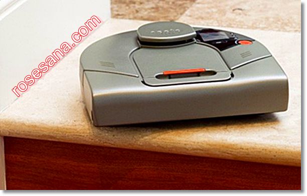
Neato XV-11 , the laser vacuum cleaner robot

Neato Robotics has debuted the Neato XV-11, which is another one of their products that will “free people from household chores.” But it doesn’t do dishes.

Basically, the Neato XV-11 gets a 360-degree view of the target room, and then maps out a cleaning plan. It follows the route, and then backtracks to get every little piece of dust from every nook and cranny it possibly can. The petite vacuum is less than four inches tall, so it should be able to fit under almost everything.

Best of all, it can be scheduled when to clean - even daily if you’re really messy. Once finished, the Neato XV-11 returns to the dock by itself for charging.

This is the only robotic vacuum that maps a room's parameters and obstacles and cleans the entire floor in the most efficient, linear pattern . An onboard laser identifies walls, furniture, and doorways, creating a digital map the robot uses to confirm where it's been, where it needs to go, and avoid obstacles that other robotic vacuums can only detect by impact. The robot begins by vacuuming a room's perimeter and continues in a human-like, back-and-forth manner without traveling over the same area more than once. 

Because of its methodical, efficient movement, the robot conserves power for its vacuum suction--the most powerful in a robotic vacuum--that removes dirt or pet hair in one pass. It repeatedly updates the map to account for objects that may have been moved or added to the room during the cleaning process and automatically moves on to the next room only when it's vacuumed every square inch. 

The robot cleans up to four rooms per charge, automatically returns to its drive-on charger when its battery runs low, and resumes cleaning where it left off once it's fully recharged. Includes an easy to remove dirt bin and two air filters. Recharges in three hours. 13" W x 12 1/2" L x 4" H

Friday, September 17, 2010

Waterproof switching power supply

Waterproof switching power supply.

available type:
QV - 80 - 12X    12V    6.7A
QV - 120 - 12X    12V    10A
QV - 180 - 12X    12V    15A
made in China switching power supply waterproof

Monday, September 13, 2010

Meanwell Switching Power Supply Industrial Standard with ISO-9001

Mean Well Enterprises Co., Ltd. is one of the leading switching power supply manufacturers in Taiwan . Established in 1982, it gained ISO-9001 certification in 1994. The product lines include AC/DC switching power supplies, DC/DC converters, DC/AC inverters and battery chargers. 
 ready stock types:
Mean Well Switching Power Supply Series


Monday, September 06, 2010

WIZ220IO - Evaluation Board

Webserver based IO control module WIZ220IO with evaluation Board Key Features of WIZ220IO module *Evaluation Board   - Remote I/O Monitoring and Control with Ethernet   - 8 Digital Input Ports   - 8 Digital Output Ports   - 2 Analog Input Ports (12 bit resolution)   - 2 Analog Output Ports (12 bit resolution)   - Supports Application Program   - Supports WebServer


Specifications(WIZ220IO)

Network Interface
10BaseT/100BaseTX Auto Negotiation (Full-duplex and half-duplex) Auto MDIX

Digital Input
Input Port 8 ports Input Type Voltage Low level input voltage -0.5V ~ 0.8V High level input voltage 2.0V ~ 5.5V

Digital Output
Output Port 8 ports Output Type Voltage Low level output voltage MAX 0.4V High level output voltage MIN 2.4V

Analog Input
Input Port 2 ports Resolution 12-bit Input Type Voltage Sampling Rate 100ksps Input Range 0 ~ 5V

Analog Output
Output Port 2 ports Resolution 12-bit Output Type Voltage Setting Time 4.5us Output Range 0 ~ 5V

Protocol
ARP, ICMP, TCP, DHCP, PPPoE, HTTP

Dimensions
63 x 45 (mm)

Power
DC 5V

Friday, September 03, 2010

VOXDE UC-800 IPPBX

VOXDE   UC-800 (Made in Taiwan)  is   an   IP   PBX   equipment   designed   for   SOHO,Small   and   Medium   Business   applications.  VOXDE UC-800      integrates up to 8 analog ports [ 6 CO Trunk / 2 Analog port or 4 CO Trunk / 4 Analog port) to support the existing analog phone lines or PSTN trunks. It provides Ethernet port for the connection to the Internet   Telephone   Service   Providers   [ITSP]   to   cut  telephone bill   when   long   distance   calls   are   routed through the Internet. VOXDE UC-800 provides the full PBX features including auto attendant, conferencing, voice   mail,   IVR,   call   forward   on   busy   or   no   answer,   blind   transfer,   supervised,  transfer,   call parking   / queuing,   music   on   hold,   remote   office   support,   etc.   It   has   a   built-in   SIP   proxy   and  supports   extension registrations and configurable dial plan. It supports SIP compliant devices as peers: IP phones, soft phones (xlite),  ATA,  Nokia  cell  phone,  IPhone,  Android   and  voice  gateways.   Web   based   configuration  and management are provided in the VOXDE UC-800. Web call feature is provided in the VOXDE UC-800.

 HARDWARE SPECIFICATIONS  
- 1 Ethernet port 
- 2 FXS / 6 FXO ports on base unit 
- 4 Configurable FXS/FXO ports 
- LED: Power, Alarm and 8 LED for FXS/FXO ports 
- Mechanical Dimension (L*W*H):165*143*25  mm 
- Power: + 12V DC 
- Temperature : 0 to 45 
- Humidity : up to 90 % non-condensing  
Features

    - Build-in SIP proxy server, support SIP compliant devices as peers: IP phones, soft phones, ATA and             voice gateways
    - Supports ITU G.711, G.726, G729, G723.1, and GSM voice codecs and echo cancellation
    - Supports basic calls, call transfer, forwarding, parking, pickup, and hunting
    - Supports voice mails, conference room
    - Supports Remote Office connections
    - Supports system expansions (Inter PBX)
    - Configurable dial plan
    - Make phone calls via SIP service providers
    - Web based configuration and management
    - Provide Web Call service (option)
    - Support recording to FTP Server.

Wednesday, September 01, 2010

TSOP34840, 40 kHz Infra Red Receiver Modules for Remote Control Systems

TSOP34840, 40 kHz Infra Red Receiver Modules for Remote Control Systems 
The TSOP348.. - series are miniaturized receivers for infrared    remote    control   systems.    PIN   diode    and
preamplifier are assembled on lead frame, the epoxy package is designed as IR filter.
The demodulated  output signal can directly  be decoded by a microprocessor. TSOP348.. is the standard IR remote control receiver series for 3 V supply voltage, supporting all major transmission codes.  
Features
•  Photo detector and preamplifier in one package
•  Internal filter for PCM frequency
•  Improved shielding against electrical field disturbance 
•  TTL and CMOS compatibility
•  Output active low 
•  Supply voltage: 2.7 V to 5.5 V 
•  Improved immunity against ambient light