Thursday, March 31, 2011

HaViMo2 - Image Processing Module (for Robotis/ Robobuilder)

HaViMo is a computer vision solution for low power microprocessors. It is equipped with a CMOS camera chip and a microcontroller which performs the image processing. The results are then accessed via serial port. In HaViMo2 several features such as frame rate are improved.

In addition to the region growing algorithm available in prior versions, a new algorithm is implemented called Griding. The algorithm is a suitable pre-processing step for many other applicationssuch as object recognition and self localization.

The compatibility area of the module is also extended to more software and hardware platforms. HaViMo2 is compatible with ROBOTIS and RoboBuilder bridges. It can also be integrated in programs developed in Roboplus. Other platforms can also communicate with the module using either half or full-duplex serial protocols.

Features:
Havimo 2.0 Camera /Vision Module for Robot
  • Integrated Color CMOS Camera
  • Frame Resolution: 160*120 Pixels
  • Color Depth: 12 bits YCrCb
  • Frame Rate: 19 Fps
  • Full Access to all CMOS Camera registers
  • Color-Based Image Processing
  • Integrated Color Look-up Table
  • On-line Region-growing
  • On-line Griding
  • Raw image output in both calibration and implementation modes
  • Supported Hardware
  • Half Duplex (ROBOTIS)
  • Full Duplex (RoboBuilder)
  • Requirements for other platforms
  • TTL level RS232
  • 115200 BAUD for Full Duplex Mode (RoboBuilder Mode)
  • 1 MBAUD for Half Duplex Mode (ROBOTIS Mode)
  • Supported Software
  • Roboplus (ROBOTIS)
  • Direct C programming (ROBOTIS)
  • RBC firmware
  • Direct C programming (RoboBuilder)

HaViMo Vision Module 1.5 for Bioloid

HaViMo is a Vision Module for Bioloid that gives the Robot the ability to detect multiple Colour BLOBs and navigate in familiar environments such as a Robocup football field or a maze autonomously. The module was developed by Berlin's Free University for the RoboCup humanoid robots of FU-Berlin, the “FUmanoids”, that won the 3 Place of the RoboCup 2007 Humanoid League in Atlanta.

Havimo V1.5 for Bioloid
The Vision Module includes a dedicated image processor capable of identifying up to 16 different color areas (BLOBs) that are pre configured by the user. For each BLOB the module maintains different parameters such as:
  • Color ID
  • Center Coordinate
  • Bounding box
  • number of pixels, etc.
The module enables a relatively low end processor such as an Atmega128 to receive simple digests of image interpretation that in turn can be used to direct the robot towards targets such as a ball or out of a labyrinth.

Highlights:

Lightweight integrated camera and image processor Controlled and queried via Dynamixel protocol (1 wire, half duplex, TTL UART) Simple and affective way to implement real time image processing and interpretation, based on color regions. Able to Acquire images and send them to a remote PC . Can even be connected to a simple microcontroller (ATMEGA, PIC, ...) and easily add the ability track objects.

HaViMo maintains a large table with about 50 parameters that some can be read and others can be read and written to. Using the Dynamixel serial protocol, the bus controller can ask HaViMo 8 times/sec to send back information regarding the state of the 16 contiguous-color-areas (stored logically in this addressable table).

Technical Details:
  • Frame rate: 8 FPS
  • Resolution: 160*120 color
  • Image noise filtering; Auto Exposure; Auto White Balance
  • Image processor: MagnaChip HV7131RP
  • (old HaViMos of version 1.0 - sold until May 31st 2009 - used a MagnaChip HV7131GP)
  • Built in color lookup table
  • Detection of up to 16 contiguous color regions at 8hz in the captured Image
  • Output Format: 256 bytes after processing of each frame, containing information about the found color regions on the image, including coordinates, dimensions,...
  • Communication Protocol: Dynamixel Standard Communication Protocol
  • Bus: One Wire TTL Bus (Interconnectable with AX-12+ servos on the Dynamixel Bus. A connector for the Dynamixel bus is mounted on board for easy assembly in the Bioloid Kit).
  • The HaViMo module can also be used with any other micro Processor that is capable of half duplex communication at 1Mbps.
(HaViMo 1.5 was designed for the Dynamixel bus which is a 1 wire, half duplex bus with a UART at TTL level).


Note: HaViMo Modules now come without the AX-12 case. They come as PCBs with holes strategically placed, to assemble it on the Bioloid Frames.

Brushless Vexta DC Motor AXH230K-5 & Driver board Package

Brushless Vexta DC Motor AXH230K-5

Specifications:
- power supply: 24VDC
- Input current: 3.4 A
- Output power: 30W
- Gear Ratio: 5
- initial Torque: 1.5 kgfcm
- Torque: 5.4 kgfcm @ 20 ~ 500r/min
- motor speed settings: internal, external potentiometer or an analog voltage (0-5VDC)
- Integrated functions: Start / Stop, Brake, Direction of rotation
- Overload, Out-of Phase, overvoltage, Undervoltage, Overspeed Protection
- Include: AXHM230K-GFH DC Motor and DC Motor Driver AXHD30K

Wednesday, March 30, 2011

Futaba S3003

S3003 is standard type servo motor by Futaba, with swivel angle 180 degrees.

Specifications:
- Torque: 44.4 oz-in @ 4.8 V or 56.9 oz-in @ 6.0 V. (4KG/cm)
- Speed​​: 0.23 sec/60deg @ 4.8 V or 0.19 sec/60deg @ 6.0 V.
- Dimensions: 1.6 x 0.8 x 1.4 ins.
- Weight: 1.3 oz.

Low Cost Super Microcontroller Trainer

Super Microcontroller Trainer is Professional Version Trainer Board module and designed so complex that a variety of applications can be implemented in it.

Features:
- 4Kb Internal Flash Program Memory for AT89S51, optionally can be used for MCU ATMega8515 ATMega8515 to add and change the jumper, optional can be used to ATMega8535 by adding a socket converter, can optionally be used for Renesas R8C by adding DST-Stamp
- Crystal Optional 12 MHz / 8 MHz
- Programming using USB (does not require a computer parallel port)
- 8 Push button
- 8 Dip Switches
- 8 LED
- RS232 Port
- 4 Channel ADC with adjustable VREF
- 1 Channel DAC with adjustable VREF
- 2x16 LCD with backlight
- + battery backup RTC
- Driver for DC Motor, Stepper Bipolar, unipolar Stepper
- 6 Seven segment with two points for the application of a digital clock
- Clock generator using PLL with frequency selection:
* Selector 1, 10 and 100 Hz
* Linear using the VR
- Pulse Generator uses TTL MMV with election timing
* Selector 50uS, 5ms, 50ms
* Linear using the VR
* Voice Amplifier + speakers 0.25W
* Buzzer
* The conditioning signal with zero offset and gain calibration
* Breadboard with 700 holes
* Add on to the printer interface
* Add on to the keyboard interface

Tuesday, March 29, 2011

USB STK300 ATmega128 AVR Starter Kit with JTAG ICE

STK300 AVR Starter Kit

AVR Development board with mounted ATmega128L
USB JTAGAVR ICE Tool - see description below
AVRISP-U USB AVR In-System Programmer

WINAVR C Compiler
WINAVR C examples - UART, Keypad, LCD, switches and LEDs
IAR Assembler - command line
AVRStudio4 IDE, Assembler and Simulator
Datasheets, schematics, manual and sample code
Embedded C book on CD
Get Going with...AVR book on CD

AVR Microcontroller Device Support

ATmega64, ATmega128, ATmega1281 and ATmega2561 have board support
Equivalent low voltage (L, V) Parts are supported down to 1.8V
Devices Supported by ISP :-
ATtiny13, ATtiny25, ATtiny26, ATtiny2313, ATtiny45, ATtiny261, ATtiny461, ATtiny84, ATtiny85, ATtiny861
ATtiny24, ATtiny44, ATtiny84 - ISP only
ATmega48, ATmega8, ATmega88, ATmega16, ATmega161, ATmega162, ATmega163, ATmega164P, ATmega165, ATmega168, ATmega169, ATmega32, ATmega325, ATmega324P, ATmega329, ATmega644, ATmega644P, ATmega645, ATmega649, ATmega8515, ATmega8535
ATmega64, ATmega128, ATmega1280, ATmega1281, ATmega169, ATmega2561, ATmega2560, ATmega3250, ATmega3290, ATmega640, ATmega6450, ATmega6490
AT90CAN32, AT90CAN64, AT90CAN128, AT90PWM2/3, AT90PWM316
See STK200ICE for socket support for 8, 20, 28 and 40-pin AVR microcontrollers.


Operating Systems

Win 2000/XP/VISTA/7 (32 and 64-bit)


STK300 AVR Board Details

ATmega128L-8AI Device mounted on daughter board avoids surface mount problems. The ATmega128L operates from 2.7-5.5V and will generally run faster than 8 MHz at higher voltages. If you require a mounted ATmega128-16AI device instead please request a quotation as there may be a small surcharge.
Easy access to all ports
Peripheral support including ADC and 2 RS232 Ports
LCD interface.
3.3V/5V operation
+10 and -10V supplies available for OP-Amp
Brownout circuitry
Real Time Clock support
External Flash RAM support
Switches and LEDs
24C EEPROM socket
JTAG and ISP connectors
Sample mounted ATMega128L device

CD Contents

AVRISP-U USB port AVR programmer software. Easy to use, full Fuse, Lockbit and Bootblock support
AVRStudio Development environment from Atmel. Includes projects, editor, assembler and simulator. This is Atmel software
WINAVR AVR C Compiler with full IDE
Manual, schematics, AVR Datasheets, sample files, circuit examples
JTAGAVR ICE documentation
Books on AVR microcontroller and Embedded C on CD
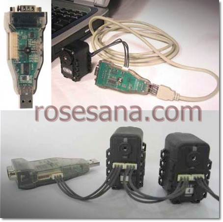

JTAGAVR ICE Tool
A real USB port In Circuit Emulator (JTAG ICE) for AVR emulation. It interfaces with Atmel AVR Studio and runs code on your AVR device. Supplied with adapters to contect directly to the port headers on the STK300 board.


Features
The JTAGAVR uses the On-chip Debug features of the newer AVR devices giving exact electrical and code feedback.
Compatible with AVR Studio 4.10 plus
Supported by Win 98, 2000, ME, XP
3 Hardware breakpoints
Step and Break on program change
Debugger and programmer
Supports Assembler or HLL source code debugging
3V to 5V operation
Atmel JTAG interface
Adapters for STK200, STK300 or STK500


JTAG ICE AVR Device Support

ATmega32, ATmega16, ATmega64
ATmega128, ATmega162, ATmega169
ATmega323, AT90CAN128


Contents

USB JTAG AVR tool
2 Adapters for STK*00 boards
USB lead
Software CD with datasheets, AVR Studio, C Compiler, books and user documentation

Protek 3110 2 Channel, 100MHz Digital Storage Oscilloscope

Protek 3110 100MHz DSO

Protek 3110 Dual-Channel, 100MHz Digital Storage Oscilloscope, Sampling Rate: 1GSa/s & Rise time: 3.5ns

  • 100MHz Bandwidth with 2 Channels
  • 1GSa Real-time Sampling Rate
  • 25GSa/s Equivalent-Time Sampling Rate
  • Large 7-inch Color Display
  • Record Length up to FFT
  • Multi-Languages Support
  • USB Host and Device Connections 
  •  
Specifications
Channels 2
Bandwidth 100MHz
Rise Time 3.5ns (Approx.)
Input Impedance Resistance: 1 M +/- 2%
Capacitance: (20+/-5) pF
Polarity Normal & Invert
Maximum Input 400V (DC + AC Peak)
Waveform Signal
Process
CH1 +/- CH2, CH1 x CH2, CH1/CH2, FFT
Bandwidth Limit 20MHz +/-% Typical
Horizontal Specifications
Sampling Rate 1GSa/s
Equivalent Max. Sampling Rate is 25GSa/S for all Times
Range
(1 - 2 - 5 Increments)
50s/div ~ 5ns/div
Mode Main Sweep, Main Sweep + Delay Expansion Sweep, X-Y
Trigger Specifications
Source CH1, CH2, EXT., EXT/5, AC Line
Mode Auto, Normal, Single
Trigger Sensitivity DC: CH1/2 (typical) 1 Div from DC to 10MHz; 1.5div from 10MHz to full
EXT (Typical): 200mV from DC to 40MHz
EXT/5 (Typical): 1V from FC to 40MHz
AC: Attenuates signal below 10Hz
HF Reject: Attenuates signals below 15kHz
LF Reject: Attenuates signals below 150 kHz
Noise Reject: Reduces trigger sensitivity
Trigger Level Range CH1, CH2: +/- Division from center of screen
EXT: +/- 1.2V
EXT/5: +/- 6V
Trigger Level Accuracy
(Accuracy is for signals having
rise and fall time at max 20ns)
CH1, CH2: +/-(0.3div x V/div)(within +/-4 Division from center of screen)
EXT: +/- (6% of Setting + 40mV)
EXT/5: +/- (6% of setting + 200mV)
Edge Trigger Rising, Falling, Rising & Falling
Pulse Width Trigger Trigger (when >, <, =) on positive or negative pulses
Pulse width range: 20ns ~ 10s
Videon Trigger Trigger on NTSC, PAL, or SECAM standard video signal
Line Range: 1-525 (NTSC), 1 - 625 (PAL/SECAM)
Slope Trigger Trigger (when >, <, =) on positive or negative slope, Set Time: 20ns ~ 10s
Overtime Trigger From the rising or falling edge, Set Time: 20ns ~ 20s
Alternative Trigger Internal Trigger on edge, pulse width, video or slope
Cursors and Measurement
Voltage Measurement Vpp, Vamp, Vrms, Vhi, Vlo, Vmax, Vmin, Pre-shoot, Overshoot
Time Measurement Frequency, Rise Time, Fall Time, Positive Width, Negative Width, Duty Cycle
Delay Measurement Delay 1- > 2
Delay 1- > 2
Cursor Measurement Voltage Difference between cursors V
Time Difference between Cursors T
Frequency difference between Cursors 1 T
Display
TFT LCD Type 7.0 Inch Diagonal Crystal Display
Display Resolution 800 x 480 Dots
General Specifications
USB USB Host / USB Device
Power Source AC 100V ~ 240V +/- 10%, 45Hz ~ 440Hz, Auto Selection
Physical Dimensions 12.3 x 4.25 x 5.6" inches (313 x 108 x 142mm)
Weight 4.6lbs (2.08Kg)

Monday, March 28, 2011

Universal Serial to serial or serial to usb Converter

Convert between USB - RS485 - RS232 - UART TTL .Universal Serial to serial or serial to usb Converter module which have universal conversion function. The RS485 communication has Multi point Mode, Full Duplex Mode (Optional), Controlled Mode and Automatic Mode. Available type of this module is half duplex and full duplex.

Features
- UART TTL to USB Converter
- UART TTL to RS232 Converter
- UART TTL to RS485 Converter
- RS232 to RS485 Converter
- USB to RS485 Converter
- USB to RS232 Converter
- Mode Auto / Manual for RS485
- RS485 Noise rejection circuit
- Adjustable pull up for RS485 line
- Mode 3.3V / 5V for USB I/O
- USB Power Enable Jumper
- RS485 Full Duplex (Optional)

Package Contain:
- DST Converter Modul
- USB Cable
- Full Duplex RJ-45 Cable
- RS232 Cable
- User Manual
- CD Software

8 Channel GSM Remote Switch

8 Channel GSM Remote Switch is ready to use electronic module that consist GSM module, 8 solid state opto-isolated relay modules and the main board. The Opto-isolated Relay Swicth controlled manually by input button, scheduled built in RTC (Real Time Clock) and or Short Message Service via GSM Network/ Cell Phone.

Technical Spec:
- 8 Port Relay Solid State 220V with opto isolated output
- Manual Input button
- 1 port ADC input
- UART Port at TTL level
- RS232 Cable
- onchip RTC (Real Time Clock)
- GSM Modem (Module)
- GSM External Antenna add on
- Built in integrated onboard regulator 9 - 24VDC
- ISP Port
- 5 sequence schedule for relay control, daily , weekly

Kit Includes:
- Board electronic Module
- GSM Antenna
- User Manual
- CD Software consist of:
- Protocol Data &  AT Command
- Dump terminal software

**GSM SIM not include

Sunday, March 27, 2011

Top3100 universal programmer

TOP3100 programmer is of small size, low power consumption, high reliability characteristic, is designed to develop SCM and burning all kinds of storage.
TOP3100 adopts universal serial and USB communication,transmission rate is high. Anti-jamming performance is good, reliable performance is extremely high, and without external power supply, especially suitable the laptop with battery power supply for outside use.
TOP3100 Universal Programmer

Features:
All drive 48pin(vpp / VCC/ GND / TTL ) , good and fast for future upgrade.
All parts are put in stanard position(from one direction and position)
 can support 2.5-6.5 V devices,
 can use USB port's power, also can access to 5V external power supply,
 through USB universal SATA interface to connect with PC, the transfer rate is 12MHz/s,
 Suit for notebook that with battery, also suitable for desktop,
 perfect over-current protection, effectively protect programmer and device from damage,
  all pins check, can check out any pin's contact state,
 48 pins, imported universal locking socket, can match any universal adapter.
 Support Operation System:  WINDOWS7 / vista / 2000 / 2003 / xp,
 plastic shell, small, light weight, low power consumption,
 can automatically detect manufacturer and model,
 SCM timing, programming speed has nothing with computer.
Software Supports: more than Top Win ver6.0

Tech Specs:
1.Software:TopWin(for windows98se/2000/m3/xp)
Real test speed(Pl 11 / 800M , windos98se , USB1 . 1):
28F320 +check 104 s
29LF320  +check 112s
P89c58 +check  5s
2.Size: 150 x 110 x 26
3.Weight: 275g
4.Power: < 2.5w (5v/500mA)
5.Locking Socket: 40 Pin,imported high-quality socket(replaceable)
 

Top2049 Universal Programmer

TOP2049-based programmer has a small size, low power consumption, high reliability, is designed for the development of various types of memory, microcontroller and programming designed for general-purpose models. TOP2049 USB universal serial port by connecting with the PC, communications, high transmission rate, interference performance, high reliability, and no external power supply, especially for battery-powered laptop out to use.
Top2049

Features:
can support 2.5 ~ 6.5V device;
USB interface, using both power, but also the external 5V power supply;
through USB universal serial port is connected with the PC, transfer rate of 12MHz / s;
that is suitable for battery-powered laptop, but also suitable for desktop use;
Perfect over-current protection, effective protection against damage and device programmer;
 USB loading capacity testing (0-10)
check all pins, you can check out any of the contact state of pins;
 48-pin imported universal locking socket, can be equipped with a variety of universal adapter;
In WINDOWS98SE/ME/2000/XP run;
plastic shell, small size, light weight, low power consumption;
manufacturers and models can be automatically detected;
microcontroller timing, programming speed has nothing to do with the computer;
Software Support: TopWin ver3.0 more

Performance and specifications:
1. Software: TopWin (for windows98se/2000/me/xp)
2. Measured speed (PIII/800M, Windos98se, USB1.1):
28F320 104 seconds to write + proofreading
29LF320 112 seconds to write + proofreading
P89c58 5 seconds to write + proofreading
3. Volume: 155 x 110 x 26
4. Weight: 275g
5. Power: <2.5w (5v/500mA)
6. Lock Block: 48 Pin socket import high quality (replaceable)

TOP2049 into the package:
1. TOP2049 host one;
2. 5V/1A power supply one (alternate);
3. SDP-UNIV-44 a universal adapter (Simple Simple);
4. PLCC32 adapter A (Simple Simple);
5. standard USB 1.1 (compatible with USB2.0) connecting cable;
6. "TOP2049 Universal Programmer" instruction book;
7. "TopWin Software Operation Manual " one;
8. supporting TopWin software CD.
Common universal adapter reference
1. SPD_UNIV-44 PLCC44 (* P44)
2. SPD_UNIV-44 SOP44 (* Q44)
3. PLCC32
4. SOP44
5. SDP-UNIV-48 TSOP48
6. SDP-UNIV-40 TSOP40
7. SDP-UNIV-i320 uBGA48

Friday, March 25, 2011

ADC chip from Maxim

An analog-to-digital converter (abbreviated ADC, A/D or A to D) is a device which converts a continuous quantity to a discrete time digital representation. An ADC may also provide an isolated measurement. The reverse operation is performed by a digital-to-analog converter (DAC).

Typically, an ADC is an electronic device that converts an input analog voltage or current to a digital number proportional to the magnitude of the voltage or current. However, some non-electronic or only partially electronic devices, such as rotary encoders, can also be considered ADCs.

The digital output may use different coding schemes. Typically the digital output will be a two's complement binary number that is proportional to the input, but there are other possibilities. An encoder, for example, might output a Gray code.


Ready stock Analog to Digital Converter chips From Maxim :
Max110 , Max111, Max113, Max120, Max121, Max132, Max134, Max135, Max138, Max139, Max146, Max147, Max149, Max152, Max153, Max155, Max164, Max170, Max176, Max178, Max181, Max182, Max186, Max187, Max188, Max190, Max194, Max195, Max196, Max198, Max199.

Friday, March 11, 2011

GWS Piezo Gyro GW/PG03

1 Axis gyroscope for Helicopter, R/C,  Robot , etc.

Technical Specification:
DIMENSION: 26.0x27.0x11.3 mm (1.02x1.06x0.45 in )

Weight: 7.0 g (0.285oz) with Plastic Case


Input Voltage: 4.8V~6.0 V

Current Consumption: 10mA

Gain Adjustment: Single rate, non-remote

Operation Temp.: -5℃ ~ 60℃

SL500F-usb ICODE/Mifare RFID reader

Being developed based on NXP RFID technology, SL500 family desktop reader/writer includes SL500L, SL500A, SL500D and SL500F with details listed in the sheet below. It supports ISO14443A, ISO14443B and ISO15693 protocol. Free SDK is provided when customer orders SL500 family desktop reader/writer, which helps an engineer to programme its own applications. The package is composed of PC_DEMO software, WinAPI and prototype description, USB driver, sample source code in C#, VC, BC, VB, PB and DELPHI

Model RFID Reader SL500
Frequency 13.56MHz
Tag supported ISO14443A ISO14443B ISO15693
Interface RS232/USB
Temperature range -20° - +50°
Dimension 110 × 80 × 26 mm
Weight 100g
System Windows 98 \ 2000 \ XP \ NT \ ME \ Vista

Models SL500L
-RS232
SL500L
-USB
SL500A
-RS232
SL500A
-USB
SL500D
-RS232
SL500D
-USB
SL500F
-RS232
SL500F
-USB
Protocol ISO14443A ISO14443A ISO15693 ISO14443A
ISO14443B
ISO15693
Tags supported FM11RF08
Ultralight
Ultralight C
Mifare Mini
Mifare 1K
Mifare 4K
FM11RF08
Ultralight
Ultralight C
Mifare Mini
Mifare 1K
Mifare 4K
DesFire
Mifare ProX
I.CODE SLI
Tag_it HFI
FM11RF08
Ultralight
Ultralight C
Mifare Mini
Mifare 1K
Mifare 4K
DesFire
Mifare ProX
AT88RF020
SR176
SRIX4K
I.CODE SLI
Tag_it HFI
T = CL Smart card
.

Wednesday, March 09, 2011

CM-510 Bioloid Controller Module by Robotis

The CM510 is the name of the new controler block. The PCB board is similar to the Bioloid Comprehensive CM5 in shape and exposed input buttons. The CM510 board is based on Atmega2561 rather than Atmega128, meaning twice the memory for programs, motions and bootloader. The CM510 plastic container block is smaller than the CM5 block (which contains space for the battery).

The 6 sides of the block expose various interfaces including 6 analog ports. The old CM5 didn't expose any I/O ports of the Atmega128.

H/W Specifications:

* Weight: 51.3g
* CPU: ATMega2561
* Operating Voltage:
1. Tolerance Range: 6.5V ~ 15V
2. Recommended Voltage: 11.1V (Li-PO 3cell)
* Consumed Current
1. When IDL : 50mA
2. Internal I/O Max. Voltage: 0.9A
3. Overall Max. Voltage: 10A (Fuse)
* Operating Temperature: -5C~70C
* External I/O Device
1. Button: 5 pcs (Reset 1, Port 1)
2. MIC (Detetcs sound): 1
3. Temperature Sensor: 1
4. Voltage Sensor: 1
* Internal I/O Device
1. 5 pin I/O Port for OLLO compatible accessories: 6
2. AX Series Dynamixel Connector: 5

CM-5 bioloid Controller module by Robotis

The CM-5 module is the nerve center of the Bioloid robotics system. It is designed to store and execute programs for controlling robots that use the AX series Dynamixels (AX-12+ smart serial actuator and AX-S1 Sensor Module). Based around Atmel's powerful and versatile Atmega128 microcontroller, its features include four Dynamixel serial ports, programmable control buttons, and status LED's (including one auxiliary programmable led). The controller board is housed in a sturdy plastic shell, which fits into a composite frame with over 100 screw holes for attaching additional hardware.

The CM-5 module can be upgraded for wireless operation by installing a Zig-100 wireless module. With the Zig2Serial adapter, you can control your Bioloid from your computer. Install Zig-100 modules in two CM-5's, and your robots can exchange data. You can even use one CM-5 as a remote to control another.

This controller does not come with a battery or cables, but these accessories and many more can be found in our Bioloid System category.

CM-700 by Robotis

CM-700 is a control module type controller with a CP , TTL / RS485 communication circuit and ZIG-110 connector. You cannot control dynamixels or other peripheral devices alone with the CM-700. You will need a SUB board. CM-700 SUB Board is composed of a power department, connector department, switch, and an additional circuit for 5 pin peripheral devices.

H/W Specification

Weight : 37.3g
Controller : ATMega2561
Working Voltage

o Allowed Range : 7V ~ 35V
o Recommended Voltage : Please refer to the above "Power Supply."

Consumed Current

o When IDLE : 40mA
o Exterior I/O Maximum Current : 0.9A
o Overall Maximum Current : 10A (Fuse)

Working Temperature : -5 ~70
Internal I/O Device

o Button : 2 sets (Reset 1, Start 1)
o Temperature Sensor : 1
o Voltage Sensor : 1

External I/O Device

o OLLO Peripheral-Device Compatible 5 pin I/O Port : 6
o 3-Pin Connector for Dynamixel using TTL Communication : 4
o 4-Pin Connector for Dynamixel using RS-485 Communication : 5

Tuesday, March 08, 2011

USB2Dynamixel

USB2Dynamixel is a device used to operate Dynamixel directly from PC.  USB2Dynamixel is connected to USB   ort of PC, and 3P and 4P connectors are installed so that various Dynamixels can be conntected. 

Also, USB2Dynamixel can be used to change from USB   ort to Serial   ort on the PC without serial   port such as notebook computer, etc.  The function is very useful in the cases when the Dynamixel exclusive controllers such as CM-2, CM-2+, CM-5, and CM-510 are connected to USB Port, or when ZIG2Serial is connected to USB   or to control robots wirelessly.

The communication mode can be selected by chaning the switch of USB2Dynamixel as below.

1. TTL Communication : Dynamixels using 3- in ort such as AX Series, AX-S1 etc.
2. RS485 Communication : Dynamixels using 4- in ort such as DX Series, RX Series, EX Series etc.
3. RS232 Communication : Controllers using serial cable such as CM-5, CM-510 etc.

Monday, March 07, 2011

New Site about Robot in Bahasa

New Site about Robot in Bahasa

A New site Launch  on March 7, 2011 in Bahasa Indonesia , This Site dedicated to Robotic In Indonesia. 
News / Articles about Robot product, component and all accessories, Robot Competition and Education, Robot Creativity and more, All in Bahasa. (Google Translate can help you , if you don't understand)
For further info , visit the new site (in Bahasa) :

http://robot-indo.blogspot.com

Tuesday, March 01, 2011

Graphic LCD 240 x 64

Graphic LCD 240x64 is a module that consists of graphic LCD 240 x 64 pixel LCD with T6963C controller for displaying text and monochrome images. This module allows users to develop applications that require media text and image viewer.

Specifications:
Dimensions: 20.7 cm (L) x 7.3 cm (W) x 3.5 cm (H).
- Able to display a monochrome image with maximum size 240 x 64 pixels.
- Complete font generator capable of displaying text with 2 choices font size is 6 x 8 pixels or 8 x 8 pixels.
- It has a parallel interface that also supports Intel's standard bus system.
- Available courses "ImageViewer2" to convert the *. BMP monochrome images into text data for use in
ASM51 assembly line program. This program can also be used to preview images on the LCD with the help of
DT-51 ™ MinSys / PetraFuz ver 3.x.
- Packed with ready-made routines in ASM51 © and examples of programs in ASM51 ©, BASCOM-8051 ©, and BASCOM-AVR ©.
- Requires 5 Volt DC power supply.

Equipment:
- 1 piece module DT-I / O Graphic LCD 240 x 64.
- 1 sheet quick start.
- 1 piece CD contains a manual, sample applications, datasheet, etc..

Blue-Link Module

Blue-Link Module is a Class 2 Bluetooth module based Bluetron BTR310 which has a range of signals up to 10 m with a profile of SPP340. This module has two interface options can be selected via configuration jumpers is a USB (virtual UART) and TTL UART. This module can function as an initiator (devices that initiate the connection) and Acceptor (devices which accept connections). Power supply modules can be taken from the path of the USB (bus powered) or external power supply (4.8 to 5.2 VDC).

Specifications:
* Dimensions : 10.8 cm (L) x 4 cm (W) x 2.1 cm (H).
* Based Bluetron BTR310 Bluetooth Module with SPP340 profile.
* Can serve as an initiator (devices that initiate the connection) and Acceptor (devices that accept connections).
* Reach the signal up to 10 m.
* Supports TTL UART interface and a USB (virtual UART).
* TTL UART communication parameters are as follows:
o Baudrate 9600 bps, 19,200 bps or 38,400 bps.
o 8 data bits.
o 1 stop bit.
o no parity bit and no flow control.
* Selection of type of interface used by the configuration jumpers.
* Using the AT Command protocol for communication with the host (PC / microcontroller).
* Choose from 8 GPIO lines that can serve as input or output that is controlled via AT Command.
* There is an option via the USB power supply (USB powered) or external power supply (4.8 to 5.2 VDC).
* Selection of power supply source that is used by setting jumpers.
* Line external power supply and TTL UART using blue terminals to facilitate connection with an external circuit.
* Available USB type A connector on-board that can be directly connected to the PC.
* There are 4 LED indicators which function as follows:
o Connected LED: lights up when the module is connected with other modules.
o Reconnect LED: lights up when the connection with other modules disturbed and re-connection attempts.
o LED CONSOLE: lit when the module is to search for other Bluetooth devices (inquiry).
o POWER LED: lights up if the power supply module into a landslide.
* There are descriptions and explanations about AT Command protocol to facilitate the use of modules.
* Available sample test program for use with USB interface and UART TTL.
* Available USB driver for connecting the module to a PC via a USB port.

Supplies Blue-Link:

* 1 unit board SPC Blue-Link (BTR310 module is mounted on the module).
* CD / DVD-ROM containing USB driver, program testing, manual, quick start

BootLoader MICRO SYSTEM AT89C51ID2 series

BootLoader MICRO SYSTEM AT89C51XXX is a single-chip microcontroller module AT89C51ID2 equipped with a bootloader so that you no longer need an additional programmer device to perform In-System Programming. In-System Programming can be done via communication channels with the help UART bootloader and software Flexible In-System Programmer (FLIP) from Atmel. This module also provides a UART communication channels for communication with computers or other devices through USB, UART TTL, or RS-232 UART.

 Specification 
* Dimensions : 11 cm (L) x 7.3 cm (W) x 1.7 cm (H).
* Based AT89C51ID2 microcontroller with features:
o Flash memory of 64 kbytes.
o 3 pieces Timer / Counter 16 bit.
o scratch pad RAM 256 bytes.
o 10 interrupt sources.
o Dual data pointers.
o 2-wire interface with a data rate of 400 kbit / s.
o X2 features to increase the speed of microcontroller 2 times (1 machine cycle = 6 clock).
o Low power (2.7 V - 5.5 V).
* This module supports other variants such as IC:
o AT89C51IC2
o AT89C51RD2
o AT89C51RB2
o AT89C51ED2
o AT89C51RC2
o AT89C51RE2
* IC are supported by this module has an internal bootloader, so you are free to replace the IC as desired.
* PLCC IC socket mounted through making it easier for the replacement IC.
* It has 32 channels Input / Output.
* Oscillator frequency of 11.0592 MHz.
* Equipped with a bootloader to assist the process of In-System Programming via the UART.
* The process of using the In-System Programming of Atmel FLIP software assistance.
* The In-System Programming can be done through USB or UART serial RS-232 (via RJ-45).
* No need for device programmers for In-System Programming.
* Equipped with an additional circuit to control the bootloader mode from the FLIP software.
* Available channels UART RS-232 communication via the USB port (via USB to RS-232 on-board) or serial port.
* There is a series reset manually via tactile switches.
* There is an option 6-12 V power supply input (through a voltage regulator on-board) or 3.3-5V (without going through the regulator).
* There is an option outputs a voltage regulator on-board 3.3 V or 5 V.
* Available voltage output terminal in accordance with output options on-board voltage regulator.

 Equipment
* 1 unit board bootloader AT89C51XXX DT-51 MICRO SYSTEM.
* 1 set of mini-USB cable (p = ± 120 cm).
* 1 set of mini USB cable.
* CD / DVD-ROM contains the datasheet, H2U (How to Use), manual, schematics

CONVERTER USB TO UART

CONVERTER USB TO UART is a converter module USB to RS-232 or USB to RS-485 supports full duplex data rate up to 500 kbps. Power supply module can be taken from the track USB (bus powered) or external 5 VDC power. In this module available LED indicators for power supply, data transmission, data reception and validity of the RS-232 signals. In USB mode to RS-232 is available 9 RS-232 signals (DCD, RX, TX, DTR, DSR, RTS, CTS and RI).

Specifications:
* Dimension : 7 cm (L) x 6 cm (W) x 1.8 cm (H)
* There are 2 options 2-way conversion (can not be shared).
o USB to RS-232.
o USB to RS-485.
* Data rates supported up to 500 kbps.
* Interface with the computer via the USB connector type B.
* Available DB-9 male connector for RS-232 interface.
* This module provides signal DCD, RX, TX, DTR, DSR, RTS, CTS and RI for RS-232 interface.
* The module is functioning as a DTE (Data Terminal Equipment) on the mode of USB to RS-232.
* Available RJ-45 connectors for RS-485 bus.
* Available configuration jumpers for termination resistors on the RS-485 interface.
* Admission data on RS-485 communication & auto power-down feature is not active if the USB in suspend state.
* When auto power down active RS-232, RS-232 driver is active if there is a valid signal on the DB-9 connector.
* Available LED indicators for power supply, receipt & delivery of data and the validity of the RS-232 signals.
* Power supply 5 VDC, can be taken from the track USB (bus powered) or DC jack (external power 5 VDC).
* Selection of the power supply source via configuration jumpers.
* Available for USB drivers.
* Equipped with a datasheet, manual, test procedures, schematics and test programs.

Equipment:

* 1 unit of DT-board I / O CONVERTER USB TO UART.
* 1 set USB cable (p = ± 150 cm).
* CD / DVD-ROM containing manual, datasheet, test procedures, schematics, test programs and websites Innovative Electronics and USB drivers

CONVERTER TCP / IP TO UART

CONVERTER TCP / IP TO UART is a 2-way serial converter module UART to Ethernet-based WIZ105SR. This module can be used for TTL to Ethernet converter, RS-232 to Ethernet or RS-485 to Ethernet. This module is properly used for LAN-based presence system with a computer as a server database and sensor monitoring via LAN.

Specifications:
* Dimension : 8.4 cm (L) x 6.4 cm (W) x 3.7 cm (H)
* Based WIZ105SR module (Serial to Ethernet Gateway).
Based o-W5100 and GC89L591A0 MQ44I.
o Supports TCP, UDP, IP, ARP, ICMP, MAC, PPPoE.
o Auto sensing 10/100 Base-T Ethernet.
o Auto MDI / MDIX.
o Available MAG JACK for cable connections with LAN network.
o UART serial interface 3.3 V TTL
o Data transfer speeds up to 230 kbps.
* Configure UART on WIZ105SR can be chosen with the help of Configuration Tool software WIZ105SR.
o Baudrate: 1200 bps-230 kbps.
o Data: 7 or 8 bits.
o Parity: none, even, odd.
o Flow Control: none, Xon / Xoff, CTS / RTS.
o UART RS-485 connection does not provide a connection flow control CTS / RTS.
* There are 3 types of 2-way conversion of TTL UART to Ethernet, UART RS-232 to Ethernet and RS-485 UART to Ethernet.
* Equipped with the level converter circuit 3.3 V to 5 V for TTL UART interface.
* Available blue 3 pin connector for RS-485 termination (COM, D +, D-) that facilitate the installation of cables for RS-485 interface.
* Available reset button to refresh the client-server connection.
* Available factory reset button can be used to restore all settings to initial conditions WIZ105SR module (default).
* Available indicator pin header for connection to a client-server.
* 5 VDC power supply through a blue 2 pin connector.
* Compatible with DT-AVR Low Cost series and support the system microcontroller / microprocessor another.
* Equipped with the Configuration Tool WIZ105SR, datasheet, manual, test program and schematic.

Equipment:

* 1 unit of DT-board I / O TCP / IP CONVERTER TO UART.
* 1 set of serial cable (p = ± 120 cm).
* 1 set wired LAN with crossover configuration (p = ± 120 cm).
* CD / DVD-ROM contains the datasheet, test programs, manuals, test procedures, schematics and software WIZ105SR Configuration Tool.

Neo RS-232 to RS-485 serial converter

NEO RS-232 TO RS-485 CONVERTER is a serial converter module UART 2 directions which can be used for converter RS-232/RS-485, TTL/RS-232 and TTL/RS-485. This module provides a selection of data direction control on RS-485 interface automatically or manually. This module supports half duplex mode or full duplex RS-485 interface. This module also provides the CTS and RTS pins can be used as flow control on RS-232 interface and TTL.

Specifications:
* Dimension : 7.2 cm (L) x 6 cm (W) x 1.8 cm (H)
* There are 3 options 2-way conversion.
o TTL/RS-232.
o TTL/RS-485.
o RS-232/RS-485.
* Supports 1200-115200 bps baudrate.
* Can be configured as DCE (Data Communication Equipment) or DTE (Data Terminal Equipment).
* In RS-232 interface and the TTL is available pin CTS and RTS to control flow control.
* In RS-485 interface control options are available at the data is automatically or manually via jumper settings.
* Available baudrate range jumper settings for automatic data direction control on RS-485 interface.
* Supports half duplex mode or full duplex RS485 interface.
* There are 2 LED indicator for receiving and sending data and an LED power indicator
* There are 2 pieces RJ-45 connectors for RS-485 bus and an RJ-12 connectors for RS-232 bus
* There is a blue 5 pin terminal for RS-485 bus, making it easier cable installation.
* Needs power supply: 5 VDC.
* Equipped with on-board voltage regulator so it can be connected with 9-12 VDC power supply.
* Available power supply input option via the blue terminals, headers, and RJ-45 connectors.
* Compatible with DT-AVR Low Cost series controllers and other support systems.


Equipment:

* 1 unit of DT-board I / O NEO RS-232 TO RS-485 CONVERTER.
* 1 set of serial cable (p = ± 120 cm).

EMS Ethernet Module

EMS Ethernet Module an ethernet communication interface module with a microcontroller / microprocessor via the SPI interface IC based ENC28J60. This module works on 5V TTL voltage levels. IC ENC28J60 on this module has been integrated with the MAC and 10 Base-T PHY that is equipped with the capability of detection and polarity correction automatically. This module is properly used for embedded web server, an embedded DHCP server and other applications based on Ethernet communication.
  
  
Specifications:
   
* Dimensions: 7.3 cm (L) x 4.0 cm (W) x 1.6 cm (H)
    * Based IC ENC28J60.
          
o Compatible with IEEE 802.3 Ethernet controller.
          
o Integrated with MAC & 10 Base-T PHY.
          
o Available 1 port 10 Base-T is equipped with automatic polarity detection and correction.
          
o Supports full duplex mode and half duplex.
          
o Shipping restarted automatically (programmable).
          
o Calculation of CRC (programmable).
          
o Rejection of the wrong package automatically (programmable).
    
SPI Interface with clock frequency up to 20 MHz and 5V TTL level.
    
* Data transfer speeds up to 10 Mbps Ethernet.
    
* Data buffer of 8 kbytes for data packets sent or received (shared buffer).
    
* Supports data packet unicast, multicast or broadcast.
    
* MAC address can be programmed.
    
* Equipped with MAG JACK equipped with a transformer and connection status indicators (links & active).
    
* Available jumpers for selecting the operating mode (full or half duplex).
    
* Using the SMD components made quite compact dimensions of this module.
    
* There is an interrupt pin to determine the received data.
    
* This module can be accessed through a header which is equipped housing so as to minimize wiring errors.
    
* 5 VDC power supply through a blue 2 pin terminal.
    
* Compatible with DT-AVR Low Cost series and support the system microprocessor / microcontroller other.
Equipment:

    
* 1 unit of EMS board ETHERNET MODULE.
    
* 1 set of LAN cables with cross-over configuration (p = ± 120 cm).
    
* CD / DVD-ROM that contains a datasheet, the test program, manual and schematic