Showing posts sorted by relevance for query shield. Sort by date Show all posts

Thursday, October 01, 2015

ARDUINO WIFI SHIELD 101

Arduino WiFi Shield 101 is a powerful IoT shield with crypto-authentication, developed with ATMEL, that connects your Arduino or Genuino Zero to the internet wirelessly. Connecting it to a WiFi network is simple, no further configuration in addition to the SSID and the password are required. The WiFi Shield 101 comes with an easy-to-use library that allows to connect your Arduino or Genuino board to the internet with few instructions. As always, every element of the platform – hardware, software and documentation – are freely available and open-source. This means that you can learn exactly how it's made and use its design as the starting point for your own projects.
  • Requires an Arduino / Genuino Zero or Uno (*) board (not included)
  • Operating voltage 5V (supplied from the host board)
  • Connection via: IEEE 802.11 b/g/n for up to 72 Mbps networks
  • Encryption types: WEP and WPA2 Security Enterprise
  • Connection with Arduino or Genuino on SPI port
  • Onboard CryptoAuthentication by ATMEL

(*)Please note that the Wifi Shield 101 is fully compatible with Arduino / Genuino Zero board. The shield has a basic compatibility with Uno but is under heavy development, using it now could have some minor issues.

Description
The Arduino WiFi Shield 101 allows an Arduino or Genuino board to connect to the internet using the IEEE 802.11 wireless specifications (WiFi). It is based on the Atmel SmartConnect-WINC1500 module, compliant with the IEEE 802.11 b/g/n standard. The WINC1500 module provided is a network controller capable of both TCP and UDP protocols. Use the WiFI library to write sketches which connect to the internet using the shield. The WiFI shield connects to an Arduino or Genuino board using long wire-wrap headers which extend through the shield. This keeps the pin layout intact and allows another shield to be stacked on top.
The Wifi Shield 101 also features an hardware encryption/decryption security protocol provided by the ATECC508A CryptoAuthentication chip that is an ultra secure method to provide key agreement for encryption/decryption, specifically designed for the IoT market.
Digital pin 7 is used as a handshake pin between the WiFi Shield 101 and the board, and should not be used.

On-board Interfaces
  • The header marked as TX/RX allows the connection to the board's hardware serial, when shorted. It can be used to upgrade the WiFi module FW through the Arduino or Genuino board.

On-board Indicators
  • The shield contains a number of signalling LEDs:
  • ON (green) : indicates that the shield is properly powered
  • WIFI (green) : indicates a connection to a network
  • ERROR (red) : indicates when there is a communication error
  • NETWORK (yellow) : indicates that data is received/transmitted

Tuesday, July 09, 2013

Arduino GSM shield

The Arduino GSM Shield allows an Arduino board to connect to the internet, make/receive voice calls and send/receive SMS messages. The shield uses a radio modem M10 by Quectel . It is possible to communicate with the board using AT commands. The GSM library has a large number of methods for communication with the shield.


The shield uses digital pins 2 and 3 for software serial communication with the M10. Pin 2 is connected to the M10’s TX pin and pin 3 to its RX pin. See these notes for working with an Arduino Mega, Mega ADK, or Leonardo. The modem's PWRKEY pin is connected to Arduino pin 7.

The M10 is a Quad-band GSM/GPRS modem that works at frequencies GSM850MHz, GSM900MHz, DCS1800MHz andPCS1900MHz. It supports TCP/UDP and HTTP protocols through a GPRS connection. GPRS data downlink and uplink transfer speed maximum is 85.6 kbps.

To interface with the cellular network, the board requires a SIM card provided by a network operator. See the getting started page for additional information on SIM usage.

The most recent revision of the board uses the 1.0 pinout on rev 3 of the Arduino Uno board.
Notes on the Telefonica/Bluevia SIM included with the shield

The GSM shield comes bundled with a SIM from Telefonica/Bluevia that will work well for developing machine to machine (M2M) applications. It is not necessary to use this specific card with the shield. You may use any SIM that works on a network in your area.

The Bluevia SIM card includes a roaming plan. It can be used on any supported GSM network. There is coverage throughout the Americas and Europe for this SIM, check the Bluevia service availability page for specific countries that have supported networks.

Activation of the SIM is handled by Bluevia. Detailed instructions on how to register and activate your SIM online and add credit are included on a small pamphlet that comes with your shield. The SIM must be inserted into a powered GSM shield that is mounted on an Arduino for activation.

These SIM card come without a PIN, but it is possible to set one using the GSM library's GSMPIN class.
You cannot use the included SIM to place or receive voice calls.
You can only place and receive SMS with other SIMs on the Bluevia network.

It's not possible to create a server that accepts incoming requests from the public internet. However, the Bluevia SIM will accept incoming requests from other SIM cards on the Bluevia network.

For using the voice, and other functions of the shield, you'll need to find a different network provider and SIM. Operators will have different policies for their SIM cards, check with them directly to determine what types of connections are supported.


Power requirements
It is recommended that the board be powered with an external power supply that can provide between 700mA and 1000mA. Powering an Arduino and the GSM shield from a USB connection is not recommended, as USB cannot provide the required current for when the modem is in heavy use.

The modem can pull up to 2A of current at peak usage, which can occur during data transmission. This current is provided through the large orange capacitor on the board's surface.

On board indicators

The shield contains a number of status LEDs:
On: shows the Shield gets power.
Status: turns on to when the modem is powered and data is being transferred to/from the GSM/GPRS network.
Net: blinks when the modem is communicating with the radio network.

On board interfaces

The shield supports AIN1 and AOUT1 as audio interfaces; an analog input channel and an analog output channel. The input, exposed on pins MIC1P/MIC1N, can be used for both microphone and line inputs. An electret microphone can be used for this interface. The output, exposed as lines SPK1P/SPK1N, can be used with either a receiver or speaker. Through the modem, it is possible to make voice calls. In order to speak to and hear the other party, you will need to add a speaker and microphone.

Wednesday, August 10, 2011

The Arduino Ethernet Shield

The Arduino Ethernet Shield allows an Arduino board to connect to the internet. It is based on the Wiznet W5100 ethernet chip (datasheet). The Wiznet W5100 provides a network (IP) stack capable of both TCP and UDP. It supports up to four simultaneous socket connections. Use the Ethernet library to write sketches which connect to the internet using the shield. The ethernet shield connects to an Arduino board using long wire-wrap headers which extend through the shield. This keeps the pin layout intact and allows another shield to be stacked on top.

The Ethernet Shield has a standard RJ-45 connection, with an integrated line transformer and Power over Ethernet enabled.

The latest revision of the shield adds a micro-SD card slot, which can be used to store files for serving over the network. It is compatible with the Arduino Uno and Mega (using the Ethernet library). The onboard microSD card reader is accessible through the SD Library. When working with this library, SS is on Pin 4.
The latest revision of the shield also includes a reset controller, to ensure that the W5100 Ethernet module is properly reset on power-up. Previous revisions of the shield were not compatible with the Mega and need to be manually reset after power-up. The original revision of the shield contained a full-size SD card slot; this is not supported.

The 6-pin serial programming header is compatible with FTDI USB cables and the Sparkfun and Adafruit FTDI-style basic USB-to-serial breakout boards. It features support for automatic reset, allowing sketches to be uploaded without pressing the reset button on the board. When plugged into a FTDI-style USB adapter, the Arduino and Ethernet shield are powered off the adapter.

Friday, June 05, 2015

Arduino 9 Axes Motion Shield

The Arduino 9 Axes Motion Shield is based on the BNO055 absolute orientation sensor. The BNO055 is a System in Package (SiP), integrating a triaxial 14-bit accelerometer, a triaxial 16-bit gyroscope with a range of ±2000 degrees per second, a triaxial geomagnetic sensor and a 32-bit microcontroller running the BSX3.0 FusionLib software. The sensor features three-dimensional acceleration, yaw rate and magnetic field strength data each in 3 perpendicular axes. It also provides the sensor fusion signals such as Quaternion, Euler angles,Rotation vector, Linear acceleration and gravity vector.


In addition, it incorporates an intelligent interrupt engine, which allows for triggering interrupts based on slow or no motion recognition, any motion (slope) detection and high-g-detection.The shield is TinkerKit compatible, which means you can quickly create projects by plugging TinkerKit modules to the board.

Power:
The Arduino 9 Axes Motion Shield has no power jack and is powered only when attached to an Arduino board.

Input and output: 
The shield features several TinkerKit input/output and communication interfaces. Connecting TinkerKit modules can simplify the creation of a project or a prototype.

Physical characteristics: 
The maximum length and width of the 9 Axes Motion Shield PCB are 2.7 and 2.1 inches respectively. Four screw holes allow the board to be attached to a surface or case. Note that the distance between digital pins 7 and 8 is 160 mil (0.16"), not an even multiple of the 100 mil spacing of the other pins.

Compatibility:
The Arduino 9 Axes Motion Shield is compatible with Uno, Yùn, Leonardo, Ethernet, Mega and Due boards. When using the Arduino 9 Axes Motion Shield, be sure to solder the Interrupt bridge and Reset bridge in the correct position depending on the board used.

Programming:
The 9 Axes Motion Shield can be programmed with the Arduino software.

Features
- Triaxial 14-bit accelerometer.
- 16-bit Triaxial gyroscope with a range of ± 2000 degrees per second.
- Triaxial geomagnetic sensor.
- 32-bit microcontroller that runs the software BSX3.0 FusionLib.

This Shield also provides the combined signals from multiple sensors such as quaternion, Euler angles, rotation vector, linear acceleration and gravity vector.

Monday, September 07, 2015

Arduino Ethernet Shield Rev3 WITH PoE Module

The Arduino Ethernet Shield with PoE (power-over-Ethernet) Module allows an Arduino board to connect to the internet. It is based on the Wiznet W5100 ethernet chip (datasheet). The Wiznet W5100 provides a network (IP) stack capable of both TCP and UDP. It supports up to four simultaneous socket connections. Use the Ethernet library to write sketches which connect to the internet using the shield. The ethernet shield connects to an Arduino board using long wire-wrap headers which extend through the shield. This keeps the pin layout intact and allows another shield to be stacked on top.

The R3 version brings to this shield the 1.0 standard pinout that consist in 4 additional pins: 2 of them placed near the AREF pin, that are used for TWI communication, and the other 2 are placed near the RESET pin. The IOREF pin is used to adapt the shield to the board on which is mounted. The last one is not connected and is reserved for future uses.

The latest revision of the shield adds a micro-SD card slot, which can be used to store files for serving over the network. It is compatible with the Arduino Duemilanove and Mega (using the Ethernet library). It also have a separate power-over-Ethernet (PoE) module that is soldered to the board to provide power from a conventional twisted pair Category 5 Ethernet cable. It is IEEE802.3af compliant, and works with all compliant PoE injectors currently available.

Technical specifications

Lenght68.6 mm
Width53.3 mm

Thursday, March 07, 2013

Arduino Ethernet Shield Rev3 WITHOUT PoE Module

The Arduino Ethernet Shield allows an Arduino board to connect to the internet. It is based on the Wiznet W5100 ethernet chip. TheWiznet W5100 provides a network (IP) stack capable of both TCP and UDP. It supports up to four simultaneous socket connections. Use theEthernet library to write sketches which connect to the internet using the shield. The ethernet shield connects to an Arduino board using long wire-wrap headers which extend through the shield. This keeps the pin layout intact and allows another shield to be stacked on top.

The R3 version brings to this shield the 1.0 standard pinout that consist in 4 additional pins: 2 of them placed near the AREF pin, that are used for TWI communication, and the other 2 are placed near the RESET pin. The IOREF pin is used to adapt the shield to the board on which is mounted. The last one is not connected and is reserved for future uses.

The latest revision of the shield adds a micro-SD card slot, which can be used to store files for serving over the network. It is compatible with the Arduino Duemilanove and Mega (using the Ethernet library). It also adds a separate power-over-Ethernet (PoE) module can be soldered to the board to provide power from a conventional twisted pair Category 5 Ethernet cable. It is IEEE802.3af compliant, and works with all compliant PoE injectors currently available.

Tuesday, September 25, 2012

TinkerKit Mega Sensor Shield V.2


The Mega Sensor Shield v.2 allows you to hook up the TinkerKit SENSORSand ACTUATORS directly to the Arduino Mega or Mega 2560 or Mega ADK, without the use of the breadboard.
It has 22 standard TinkeKit 3pin connectors. The 10 labeled I0 through I9are Analog Inputs. The ones labeled O0 through O5 are Analog Outputsconnected to the PWM capable outputs of the Arduino Board (it is possible to change these to Digital Inputs, in which case they will report either HIGH or LOW, but nothing in between).


On a Standard Arduino Mega 2560 board the pins are:
Pin 11 on the Arduino Mega is O0 on the shield.
Pin 10 on the Arduino Mega is O1 on the shield.
Pin 9 on the Arduino Mega is O2 on the shield.
Pin 6 on the Arduino Mega is O3 on the shield.
Pin 5 on the Arduino Mega is O4 on the shield.
Pin 3 on the Arduino Mega is O5 on the shield.

The one labeled IO (D13, D12, D8, D7, D4, D2) are Input / Output pins capable of PWM, digitalRead and digitalWrite. They correspond to Digital 13, 12, 8, 7, 4, 2.

Module description: A green LED signals that the shield is correctly powered.
The 4pin TWI socket allows communication to any device supporting the I2C protocol through the Wire library on Arduino. 5V and Ground are provided on the socket.
4 4pin SERIAL socket allows the board to communicate with other devices that support serial communication. 5V and Ground are provided on the socket for your convenience.

Tuesday, August 18, 2015

Weather Shield

 The Weather Shield is an easy to use Arduino shield that grants you access to barometric pressure, relative humidity, luminosity and temperature. There are also connections on this shield to optional sensors such as wind speed, direction, rain gauge and GPS for location and super accurate timing.

These Weather Shields utilize the HTU21D humidity, MPL3115A2 barometric pressure, and ALS-PT19 light sensors and relies on the HTU21D and MPL3115A2 Arduino libraries. Each shield comes with two unpopulated RJ11 connector spaces (for optional hook up of rain and wind sensors) and a 6-pin GPS connector (for optional hook up of a GP635T GPS module). Finally, each Weather Shield can operate from 3.3V up to 16V and has built in voltage regulators and signal translators.

Note: The Weather Shield comes as a stand-alone board. Headers, connectors, and additional sensors will need to be purchased separately, check the related items or wish list below!

Note: This shield was designed for the SparkFun Redboard and Arduino Uno and will not work with other boards (like the Arduino Yun, for example) without modification.

Features:

  • Humidity/Temperature Sensor - HTU21D
  • Barometric Pressure - MPL3115A2
  • Light Sensor - ALS-PT19

Friday, April 25, 2014

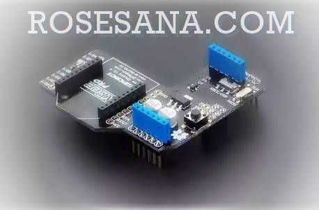
Xbee Shield for Arduino and compatibles.

XB Shield / Xbee Shield / Zigbee Shield is an add-on / Shield module to Innoduino or Arduino ™ / Arduino ™ Compatible . By using this shield then the XBee ® / XBee - PRO ® module can be easily connected (plug and play) to the Arduino ™ modules / Arduino ™ Compatible, without having to worry about the voltage levels and layout of pin connections . Furthermore freedom in determining the type of XBee that will be used are available , because the XB shield  is compatible with XBee ® and XBee - PRO ® .


specifications :
  • Supporting the XBee ® / XBee - PRO ® OEM RF Module (separate purchase)
  • Has 1 pin input lines and 8 pin input / output that can be configured ( 7 of which can also be used as analog inputs ) .
  • Has a 2 pin PWM output lines can also be configured .
  • Requires power supply for the module : 3.3 & 5 VDC .
  • Integrated with a series of LED indicators .
  • Available for Antenna holder , if using XBee ® that does not have a chip antenna .
  • Has a pin layout that corresponds to the module Arduino or Arduino Compatible .
  • There is a sample program to test the function module XBStest.ino .
  • Provided also XCTU setup.exe application to configure the XBee ® / XBee - PRO ® .
  • Dimensions : 6.1 cm  x 6.05 cm  x 2.9 cm 

Thursday, January 14, 2016

Teensy Arduino Shield Adapter

 The Teensy is an amazing and compact development platform in a breadboard friendly form factor, but what if you could incorporate it into the Arduino architecture? The Teensy Arduino Shield Adapter allows you to attach your Teensy and utilize your favorite Arduino shields without the requirement of a breadboard or any complicated wiring. Needless to say, the Teensy Arduino Shield Adapter is a useful tool for upgrading all of your existing Arduino projects to a more powerful controller!

As we stated before, the Teensy Arduino Shield Adapter provides basic Arduino compatibility with your run-of-the-mill shield but there are a few other fun features that we’ve added on, as well. These features include a Real Time Clock (RTC) battery, a JST battery connector, a 4-12V barrel jack connector, an ICSP header, and more. Because this board is simply an adapter, there is no special programming required to start working with the adapter. You will, however, need to program the Teensy for any Arduino shield you’d like to work with.

While the adapter design can fit the Teensy LC footprint, it has been designed to fully utilize the features of the Teensy 3.1. Not all of the features available on the adapter are compatible with the LC so please be sure to check the Hookup Guide in the Documents section below to ensure functionality for your project.

Note: The Teensy Arduino Shield Adapter comes as a kit and will need to be soldered together.

Features:

  • Arduino R3 Interface
  • Real Time Clock Battery
  • JST Battery Connector
  • Barrel Jack
  • I2C Jumpers
  • ICSP Header
  • DAC Pin Header

Wednesday, December 02, 2015

Arduino Ethernet Shield with PoE Module

Shield Arduino ethernet latest version of the module that has been integrated PoE (power-over-Ethernet). Based Wiznet W5500 ethernet chip which has the ability to interface ethernet with TCP and UDP protocols include internal 32K buffer. PoE module allows Arduino shield along to be able to operate in standalone utilizing active Ethernet data path as its power supply. Additional features of the shield is the presence of a micro-SD slot which can be used for file storage that can be accessed via ethernet. Ethernet library already included in the Arduino IDE so it will be very easy to start using.

It also includes a reset controller, to ensure that the W5100 Ethernet module is properly reset on power-up. Previous revisions of the shield were not compatible with the Mega and need to be manually reset after power-up. The reset button on the shield resets both the W5100 and the Arduino board.

Arduino communicates with both the W5100 and SD card using the SPI bus (through the ICSP header). This is on digital pins 11, 12, and 13 on the Duemilanove and pins 50, 51, and 52 on the Mega. On both boards, pin 10 is used to select the W5100 and pin 4 for the SD card. These pins cannot be used for general i/o. On the Mega, the hardware SS pin, 53, is not used to select either the W5100 or the SD card, but it must be kept as an output or the SPI interface won’t work.

Note that because the W5100 and SD card share the SPI bus, only one can be active at a time. If you are using both peripherals in your program, this should be taken care of by the corresponding libraries. If you’re not using one of the peripherals in your program, however, you’ll need to explicitly deselect it. To do this with the SD card, set pin 4 as an output and write a high to it. For the W5100, set digital pin 10 as a high output.

Shield Specifications:
Chip: Wiznet W550 with a 32K buffer
Dimensions: 2.7 x 2.1 inches
Additional features: microSD slot, 5 status LEDs, pin additional interface (TWI 2x, 2x output, 2x input)

PoE Module Specs:

  • Standardization: IEEE802.3af
  • Input voltage: 36V - 57V
  • Protection: Overload and short-circuit
  • Voltage: 12V
  • Efficiency DC-DC Converter: High efficiency 85% typ @ 80% load
  • Isolation: 1500V isolation (input to output)

Tuesday, October 02, 2012

Robot Tank Shield


DT-Robot Tank Shield is a shield / add-on module for Inoduino DT-AVR, Arduino ™ Mega, Arduino ™ UNO and Arduino compatible module. With this shield, the modules can Arduino tank robot evolved into a powerful platform that is ready to be developed for a variety of robotics applications. In the kitchen runway, used dual full H-Bridge driver with a motor that has a robust gearbox made of metal and precision. On both legs used 2.4 cm diameter aluminum wheels wrapped by belt drive wheel serrations track quality.

Use of this shield is easy, simply by combining DT-Robot Tank Shield with DT-AVR Inoduino module, Arduino ™ UNO or MEGA, the robot tank kit is ready to use. Application development is more challenging and interesting to use this shield include Wireless RF Remote Tank the article and the program has been included on the product DVD. Other applications that can be developed include WiFi or Bluetooth Remote Robot, Android mobile robot, Image Tracking Robot, Robot fire and so forth.

Specifications:
  • Based dual full H-bridge driver capable TB6612FNG continuous drain current up to 1.2 A of each driver.
  • Using the form of two drive motors with gear box made of metal.
  • Having a pair of cog aluminum inner diameter 2.4 cm.
  • Has the form of a belt drive outside the circular track and 10 pieces of supporting quality wheels.
  • Frame yellow solid metal body.
  • Using technology with SMD components and PCB through hole double layer.
  • The module requires a working voltage of 5 VDC obtained from the board Arduino ™.
  • Motor requires external working voltage of 5 VDC.
  • There are holes for easy access reset button board Arduino ™.
  • Equipped with the L key to help install the wheels.
  • Supplied TestTank.pde demo program contains algorithms Robot Tank applications.
  • Also provided examples of AN (Application Note) Remote Tank Tank can control the robot wirelessly RF and its source code program.
  • Compatible with DT-AVR Inoduino.
  • Compatible with Arduino ™ Uno and Arduino ™ Mega.
  • Dimensions: 16 cm  x 10.4 cm  x 6.5 cm 

Friday, July 20, 2012

DFRduino Mega 1280 (Arduino Mega 1280 Compatible)

The DFRobot DFRduino ATMega1280 MEGA USB Microcontroller is a microcontroller board based on the ATmega1280 integrated circuit. It 00% same as the original Arduino Mega.It has 54 digital input/output pins (of which 14 can be used as PWM outputs), 16 analog inputs, 4 UARTs (hardware serial ports), a 16 MHz crystal oscillator, a USB connection, a power jack, an ICSP header and a reset button. It contains everything needed to support the microcontroller; simply connect it to a computer with a USB cable or power it with an AC-to-DC adapter or battery to get started. The Mega is compatible with most shields designed for the Arduino Duemilanove or Diecimila. The DFRobot ATMega1280 MEGA USB Microcontroller can be powered via the USB connection or with an external power supply. The power source is selected automatically. External (non-USB) power can come either from an AC-to-DC adapter (wall-wart) or battery. The adapter can be connected by plugging a 2.1mm center-positive plug into the board's power jack. Leads from a battery can be inserted in the Gnd and Vin pin headers of the POWER connector. This board is almost identical to the Arduino MEGA with the exception of the color of the PCB.

Specifications
  • Microcontroller ATmega1280
  • Operating Voltage 5V
  • Input Voltage (recommended) 7-12V
  • Input Voltage (limits) 6-20V
  • Digital I/O Pins 54 (of which 14 provide PWM output)
  • Analog Input Pins 16
  • DC Current per I/O Pin 40 mA
  • DC Current for 3.3V Pin 50 mA
  • Flash Memory 128 KB of which 4 KB used by bootloader
  • SRAM 8 KB
  • EEPROM 4 KB
  • Clock Speed 16 MHz


Shield Compatibility

The Mega is designed to be compatible with most shields designed for the Diecimila or Duemilanove. Digital pins 0 to 13 (and the adjacent AREF and GND pins), analog inputs 0 to 5, the power header, and ICSP header are all in equivalent locations. Further the main UART (serial port) is located on the same pins (0 and 1), as are external interrupts 0 and 1 (pins 2 and 3 respectively). SPI is available through the ICSP header on both the Mega and Duemilanove / Diecimila. Please note that I2C is not located on the same pins on the Mega (20 and 21) as the Duemilanove / Diecimila (analog inputs 4 and 5).

The Mega is compatible with
  • Arduino Mega Prototype Shield
  • Arduino I/O Shield
  • Arduino LCD Shield
  • Arduino Motor Shield

The Mega is NOT compatible with 'Arduino Ethernet Shield'

Tuesday, January 14, 2014

Mega IO Expansion Shield V2.3 For Arduino Mega

This is version 2.3 of the Mega IO Expansion shield. This shield is extra large and includes 3 Xbee slots, 1 microSD slot, Arduino shield headers to plugin most Arduino shields. It also includes a prototyping area and breakouts for Digital pins 14 to 53, Analog pins 6 to 15 and PWM pins 2 to 9. This shield can be a major communications hub for your projects.


Specifications
  • support most of the arduino shield
  • compatible with the Arduino Mega boards/DFRobot ADK/Arduino ADK
  • Extended TTL connection pins for four Serial ports
  • DIP prototyping area makes it easy to add more chips or electronic components
  • 3 Xbee slots
  • 1 microSD slot
  • power selector to select between Arduino Mega power or external power
  • Size:125 x 57 mm

Monday, October 01, 2012

Robot Line Tracking Shield


DT-Line Tracking Robot Shield is a shield / add-on module for DT-AVR Arduino ™ Inoduino or other modules in order to be a line tracking robot kits are agile and reliable. Shield is already integrated with the line sensor and motor driver that can be freely controlled by the controller. The movement of the robot kit is powered by 2 pieces of aluminum wheels are directly connected to the motor gearbox.
Use of this shield is easy, simply by combining DT-Line Tracking Robot Shield with DT-AVR module Inoduino, the line tracking robot kit is ready for use.

Shield comes with 2 pieces of phototransistor SFH300 pantualan that serves as a detector of light from LED 1 piece. In the kitchen runway, used dual full H-Bridge motor driver TB6612FNG with fitted gearbox made ​​of metal. While both legs, using 2.4 cm diameter aluminum wheels are wrapped with a layer of quality red rubber.

Specifications:

  • Using two-Silizium-sensor NPN phototransistors (SFH 300) as receiver of a red LED light.
  • Based dual full H-bridge driver capable TB6612FNG continuous drain current up to 1.2 A of each driver.
  • Using the form of two drive motors with gear box made ​​of metal and aluminum wheels with a diameter of 2.4 cm.
  • The module requires a working voltage of 5 VDC obtained from the board Arduino ™.
  • Motor requires external working voltage of 5 VDC.
  • Have some pad that can be used for laying the connector or a simple circuit.
  • There are holes for easy access reset button board Arduino ™.
  • Equipped with the L key to help install the wheels.
  • Supplied LineTracking.pde demo program contains algorithms line tracking application.
  • The configuration process can be done easily using a GUI program help Inoduino LT-bot.exe.
  • Dimensions: 12 cm x 5.3 cm  x 5.2 cm

Wednesday, February 01, 2017

Xbee Shield for Arduino

XBee Shield for Arduino is a module / shield is designed to allow you to add a variety of wireless communication such as wifi, Bluetooth, and Zigbee into the Arduino microcontroller board.
With the shield, you can directly connect to an Arduino XBee module through the socket provided on this shield. In this module has also been accompanied by a voltage converter 5 V - 3.3 V internal, making it safe for your XBee modules.
In addition to supporting the XBee, this shield also supports some wifi and bluetooth module, such as wifi bee, bee bluetooth 2.0, bluetooth 4.0 bee, and also ESP8266 wifi bee.

Specification:
- Kompabilitasa; XBee Series 1 (standard and pro), the XBee Series 2 (standard and pro), ESP8266 wifi bee, bee bluetooth 2.0, bluetooth 4.0 bee
- Can be coupled directly to an Arduino Uno, Arduino Leonardo, Arduino Duemilanove
- Programming can be done wirelessly
- Equipped with a jumper to move the communication between a PC to an Arduino XBee


Friday, April 29, 2016

MyoWare Cable Shield

The MyoWare Muscle Sensor is now designed to be wearable allowing you to attach biomedical sensor pads directly to the board itself. However, there still may be cases where you want to mount the sensor pads away from the other hardware, this is where the MyoWare Cable Shield comes in. This shield provides a 3.5mm jack where you can attach a three electrode sensor cable allowing you to test and use the MyoWare Muscle Sensor without actually attaching it to your person.

The MyoWare Cable Shield is equipped with two rows of 3-pin plated through holes on each end of the board. This allows for standard 0.1" headers to be used to stack the shield with other MyoWare boards.

The MyoWare Muscle Sensor, that this shield attaches to, is an Arduino-powered, all-in-one electromyography (EMG) sensor from Advancer Technologies. The MyoWare board acts by measuring the filtered and rectified electrical activity of a muscle; outputting 0-Vs Volts depending the amount of activity in the selected muscle, where Vs signifies the voltage of the power source.

Tuesday, January 14, 2014

Arduino PiShield

Arduino PiShield is an add-on module for the Raspberry Pi ® module that can be used to bridge the Raspberry Pi ® module with module shield or Arduino shield ( Arduino ™ Compatible) . By using this module , Raspberry Pi ® can easily be connected to the module shield or Arduino shield / Arduino ™ Compatible without having to worry about different levels of voltage and pin connection layout .


specifications :
  • Has a pin layout that corresponds to the module Raspberry Pi ® , shield Arduino and Arduino Compatible shield .
  • Integrated with IC TXS0108EPWR as modifier voltage levels 3.3 V to 5V or otherwise on pin I / O.
  • It supports bi - directional I / O.
  • Equipped SELECT VI / O voltage levels to choose between 3,3 V or 5V on pin I / O.
  • Has a hole spacer to hold the module to the other modules that are not easily dislodged if multilevel interchanges .
  • Available WiringPi © v2 library to simplify porting pin sequence .
  • Dimensions : 6.4 cm ( P ) x 5.65 cm ( L ) x 1.9 cm

equipment:
  • 1 piece - DT module Arduino Proto PiShield .
  • 1 piece Companion DVD that contains support files

Tuesday, October 02, 2012

RF 433MHz Transceiver Shield


EMS RF Transceiver Shield is an Arduino ™ compatible module that can be used for wireless data transmission. EMS Shield RF Transceiver is designed as an add-on module for the DT-AVR Inoduino. The installation process can be done easily without having to use jumper cables. DT-AVR Inoduino addition, with respect to the allocation pinout, this module can be used with an Arduino board Arduino ™ ™ or other compatible.

EMS Shield RF Transceiver designed based RFM12S 433MHz RF modules, wireless communication module with the 433 MHz frequency and distance of communication that reaches 150 meters. RFM12S 433MHz using the SPI interface to pengaksesannya by various controller modules. EMS RF Transceiver Shield suitable for use in remote control applications, telemetry systems, or other applications where cable installation is difficult to do.


specifications:

  • Based RFM12S 433MHz RF modules.
  • Working voltage: 5 VDC.
  • Working frequency: 433 MHz.
  • Communication distances> 150 meters (receiver bandwidth = 67 kHz, transmitter freq. Deviation = 45 kHz, data rate@1.2 kbps, in an open area.).
  • Data transmission speed: up to 115.2 kbps.
  • Interface: SPI.
  • Has 4 optional pin that can be connected to pin 32, 33, 37, 38 on board Inoduino DT-AVR, Arduino ™, or other Arduino ™ compatible support.
  • Integrated with connectors to connect antenna (antenna 433 MHz include in the sales package).
  • Antenna pad is provided to connect the antenna designed by the user.
  • Equipped with EMI filter to reduce electromagnetic interference interference.
  • It has a low current consumption (standby, <0 .3=".3" li="li" ua="ua">
  • There are examples of applications using RF Transceiver Shield EMS to control robot tanks.
  • Dimensions: 8 cm x 5.3 cm  x 2.1 cm


Thursday, March 07, 2013

Arduino WiFi Shield (Integrated Antenna)

The Arduino WiFi Shield (Integrated Antenna) connects your Arduino to the internet wirelessly. Connect it to your wireless network by following a few simple instructions to start controlling your world through the internet. The Arduino WiFi Shield allows an Arduino board to connect to the internet using the 802.11 wireless specification (WiFi). It is based on the HDG104 Wireless LAN 802.11b/g System in-Package. The WiFi Shield can connect to wireless networks which operate according to the 802.11b and 802.11g specifications. There is an onboard micro-SD card slot, which can be used to store files for serving over the network.


Features
• Requires and Arduino board (not included)
• Connection via: 802.11b/g networks
• Encryption types: WEP and WPA2 Personal
• ICSP headers
• FTDI connection for serial debugging of WiFi shield


Technical Specs:

• Operating voltage: 5V 
• Connects your Arduino to the internet wirelessly
• Mini-USB for updating WiFi shield firmware
• On-board micro SD slot