Showing posts with label Programmer. Show all posts

Tuesday, June 28, 2022

HILO Systems ALL-300G2 High Performance Universal Gang Programmer

HILO Systems ALL-300G2 High Performance Universal Gang Programmer 


The only universal gang programmer that supports UFS devices

  • New design of high performance hardware provides high speed, high quality parallel programming
  • Support all types of latest UFS interface devices. The fastest UFS programming speed in the industry
  • With new integrated design, ALL-300G2 support all types of devices which are already supported on the previous model
  • Support USB 3.0 Gen 1(5 Gbps) interface to significantly increase the programming speed
  • Program up to 16 devices simultaneously 1
  • Fast new device support by request from customer
New generation high performance core

 New integrated design

Integrate hardware of previous model programmers,
support all types of devices which are already
supported on the previous models

Supports all types of device including
MCU / MPU, EEPROM, eMMC, eMCP, SPI Memory,
NOR / NAND Flash, FPGA, CPLD, etc…


Support latest UFS interface device
  • Support UFS device by only changing PACK
  • Support UFS interface (UFS 2.0, UFS 2.1, UFS 3.0),
  • support 2 Lane Gear 3 (Rate A / Rate B)

3 times faster than previous model in case of high-density memory such as eMMC and NAND devices

Support wide range of IC types
True universal hardware and software design supports a variety of IC including MCU / MPU, EEPROM, eMMC, eMCP, SPI memory, NOR / NAND flash, FPGA, CPLD, etc…

Support wide range of IC packages
  • High-quality manufactured socket board greatly extends the lifetime of usage
  • Support up to 8 socket boards, up to 16 sockets
  • 1 socket per socket board (HD-xxx-xxx2/UHD-xxx-xxx) or 2 sockets per socket board (UHD2-xxx-xxx)

User-friendly and easy to use software
  • Graphic operating interface
  • Clearly display of each function in the entire programming procedure
  • Display details and status of each device during programming
Expansion flexibility for production
Connect up to 8 units of ALL-300G2 to achieve 128 devices programming at same time 2


Specifications
Device supported MCU / MPU, EEPROM, UFS, eMMC, eMCP, SPI memory, NOR / NAND flash, FPGA, CPLD, etc…
Package supported SOP, TSOP, QFP, BGA, QFN, SON, WLCSP, etc...
Support IC pin count 8 pins ~ 300 pins
Socket number 8 socket boards, up to16 sockets total 1 socket per socket board (HD-xxx-xxx/UHD-xxx-xxx) or 2 sockets per socket board (UHD2-xxx-xxx)
Key functions Load File, Read Master, Program, Verify, Auto, ID Check, Checksum, Blank Check, Erase, Secure, Protect/Unprotect, Edit, Function Configuration, Self Test, etc…
File transfer interface USB3.0 Gen 1(5Gbps)Super Speed / USB 2.0 High Speed
Compatible OS Windows XP, 7, 8, 8.1, 10
Power AC 100 - 240V / 50 - 60Hz
Power consumption 150W
Operating Temp. 0 ~ 40℃ (32 ~ 105℉)
Dimension
W x D x H: 205mm x 250mm x 161mm (w/ PACK-ALL)
W x D x H: 205mm x 250mm x 164mm (w/ PACK-UFS)
Weight 3.5 kg
 
Notes
1Only with UHD2-xxx-xxx
2May cause drop of programming speed

Thursday, July 06, 2017

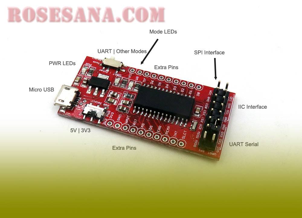
CH341 USB Programmer Convert Flash Board, USB, TTL, IIC, SPI, etc

USB programmer all-in-one chip-based CH341 that can be used to convert USB interface on PC to I²C, TTL, USB, SPI, UART and so on, so that PC can communicate and do programming to microcontroller or other development tool.

Features:
- Supports working voltage 3.3 V / 5 V.
- Supports I²C interface, USB, UART, SPI, parallel, print port, TTL, etc.
- Supports full USB function - TTL
- Equipped switch to select working mode (UART / other)
- In "UART" mode device detected as serial port, while in "other" mode device detected as external device.

Wednesday, July 05, 2017

ST-LINK V2 in-circuit debugger/programmer for STM8 and STM32

ST Link V2 Programmer is an in-circuit programmer as well as a debugger for the family of STM8 and STM32 microcontrollers. This module communicates with microcontroller using Single Wire Interface Module (SWIM) interface and JTAG / Serial Wire Debugging (SWD). The module also features full-speed USB to communicate with ST Visual Develop / ST Visual Basic (STM8) software and Keil® / Atollic® / IAR® / TASKING (STM32) software.

Features:
- Using a design resembles a flash that is easy to carry anywhere
- Equipped with aluminum alloy case that will provide protection against impact, dirt, and dust
- Can function as a programmer as well as debugger
- Compatible with STM8 and STM32 microcontrollers
- Compatible with ST Visual Develop / ST Visual Program (STM8) software and Keil® / Atollic® / IAR® / TASKING (STM32) software.
- Equipped full-speed USB to communicate to programming software
- Equipped SWIM and SWD interface to communicate to microcontroller
- Supports working voltage 3.3 V and 5 V
- Equipped with internal resetable fuse 500 MA
- Equipped LED indicator

Saturday, January 14, 2017

Mini PICkit 2 & MCU Universal ZIF socket

Kit programmer for microcontrollers from Microchip. This kit is compatible with various types of microchip microcontroller like PIC, dsPIC, PIC32, etc.
Specification:
- Power supply: +5 VDC (from USB)
- Compatible with a variety of chips from Microchip
- It has 3 LEDs as indicators (power, target, Busy)
- Has 1 buttons are used to start programming
- Available Universal ZIF socket for easy programming the chip in various packaging
- The sales package includes: 1x mini USB cable, 1x cable with two 6-pin connector, 1x 6-pin cable connector to RJ11, 2x male and 1x female header header
- Compatible with Windows 98 SE, Windows XP, or Windows XP

Sunday, October 30, 2016

SimpleLink SensorTag Debugger DevPack - CC-DEVPACK-DEBUG

The Debugger DevPack adds debug capability to your SensorTag. Plug it into the SensorTag DevPack expansion header and debug your SensorTag with Code Composer Studio or IAR ARM development environments. The Debugger DevPack includes a FREE license of Code Composer Studio that is tied to the DevPack.
The Debugger DevPack includes a USB power connection, making it easy to power your SensorTag during debugging. Alternatively, simply connect it to a USB power supply if your sensor application requires permanent power. It also includes traces for three Grove connectors to make it easy to add support for any of the 100s of Grove sensors and actuators.
The Debugger DevPack is a small form-factor XDS110 debugger. Click here to get some more information about how to use it with IAR and CCS.

Thursday, September 01, 2016

microUSB-PA5 adapter

Adapter for programming the micro USB, from the USB port to Serial UART Bridge.

specifications:
- USB 2.0, up to a maximum speed of 12 Mbps.
- Supports hardware or Xon / Xoff handshaking, 300 bps to 3 Mbps.
- Supports UART, 7 or 8 data bits, 1-2 Stop bits.
- Virtual COM Port Drivers who memungkan working with COM port available PC
- Supports Windows 98 and above, MAC (OSX-8 and above) and Linux (2.4 kernel and above)
- Powered by USB
- Working temperature between -40 ° C to 85 ° C
- Dimensions: 33.7mm x 17.3mm
- Equipped with LED indicator
- Power supply 3.3 V - 5 V
- Features Equipped with LED indicator
- Interface or port UART and USB
- USB converter - UART

Sunday, January 31, 2016

XNUCLEO-F302R8 Package A

This development kit includes :


  • XNUCLEO-F302R8 (STM32 Development Board, Supports Arduino, Compatible with NUCLEO-F302R8)
  • IO Expansion Shield (Provides interfaces for connecting XBee, WiFi-LPT100, and sensors)
  • Sensors Pack (Gas, Color, Flame, Hall, IR, UV, Laser, Sound, Temperature and Humidity, Tilt, Liquid level, etc.)


XNUCLEO-F302R8 Features

  • Compatible with NUCLEO-F302R8, onboard Cortex-M4 microcontroller STM32F302R8T6
  • Arduino connectivity support, easy to connect with various Arduino shields and access the massive Arduino resources
  • ST Morpho headers provide full access to all STM32 I/Os, easy for peripheral expansion
  • Supports mbed, build prototype quickly by mbed SDK and online tools
  • Comprehensive free software HAL library including a variety of software examples
  • Comes with a separated ST-LINK/V2 module


CompareXNUCLEONUCLEORemarks
Arduino compatibilityUNO, LeonardoUNOXNUCLEO can be configured by jumper to compatible with UNO (default) or Leonardo
Arduino ICSP interfaceYesNoneICSP is required by certain kinds of shields
USB connectivityYesNoneThe USB connector of NUCLEO is for debugging ONLY, not available for USB connection
USB connectorMicro USBMini USBMicro USB is the advanced USB standard
Morpho headers markMostNoneNow you can check the PCB mark instead of datasheet
Common interfaces are connected viaJumpers0Ω resistorsJumpers are much easier to use, need no soldering
UART debuggingAvailable while in-circuit debuggingNot available while in-circuit debuggingThe NUCLEO integrated ST-LINK/V2 functional chip can be simulated as serial port, however, it's not available while in-circuit debugging, whereas XNUCLEO features a stand-alone USB TO UART chip.
8MHz crystalYesNoneTimer is more accurate when using external 8MHz crystal
32.768KHz crystalYesNoneRequired for RTC
USB fuseYes (500mA)NoneThe computer USB interface might be harmed without fuse
LEDs41The more LEDs, the easier to monitor program running status
UART indicatorYesNoneData communication is visible now
DC inputYesNoneA convenience
Button positionClose to PCB edgeClose to Arduino connectorThe button won't be untouchable when connecting with an Arduino shield if it were close to the PCB edge
ST-LINKSeparatedIntegratedST-LINK can be used anywhere else
Comes with USB cableYesNone


  1. STM32F302R8T6
    • Core : ARM® 32-bit Cortex™-M4
    • Operating frequency : 72MHz
    • Operating voltage : 2.0V-3.6V
    • Package : LQFP64
    • Memories : 64kB Flash, 16kB SRAM
    • Interfaces : 2 x SPI, 3 x USART, 3 x I2C, 1 x CAN, 1 x USB
    • AD/DA : 1 x AD (12 bit), 1 x DAC (12 bit)
  2. SPX3819M5 : 3.3V voltage regulator
  3. AMS1117-5.0 : 5.0V voltage regulator
  4. CP2102 : USB to UART convertor
  5. Arduino connector : for connecting Arduino shields
  6. ICSP interface : Arduino ICSP
  7. USB TO UART : for debugging
  8. USB connector : USB communication interface
  9. SWD interface : for programming and debugging
  10. ST Morpho headers : access to VCC, GND and all the I/Os, easy for expansion
  11. 6-12V DC input
  12. User button
  13. Reset button
  14. Power indicator
  15. User LED
  16. 500mA fast self-recovery fuse
  17. Serial port Rx/Tx indicator
  18. 8MHz crystal
  19. 32.768KHz crystal
  20. ADC/I2C selection jumper
    • short A and B : Arduino A4, A5 is used as I2C
    • short B and C : Arduino A4, A5 is used as ADC
  21. UART selection jumper
  22. MCU current test jumper : for low power tests
  23. Power selection jumper
    • short 5V and U5V : powered from USB connection
    • short 5V and E5V : powered from external power supply
  24. USB enable jumper
    • short the jumper to enable
    • open the jumper to disable
  25. User button jumper
    • short the jumper to connect to I/Os used in example code
    • open the jumper to connect to other custom pins via jumper wires
  26. User LED jumper
    • short the jumper to connect to I/Os used in example code
    • open the jumper to connect to other custom pins via jumper wires

Friday, January 15, 2016

Silicon lab usb debug adapter DEBUGADPTR1-USB

The USB Debug Adapter provides the interface between the PC’s USB port and the C8051Fxxx’s in-system debug/programming circuitry.

The attached 10-pin debug ribbon cable connects the adapter to the target board and the target device’s debug interface signals (the USB Debug Adapter supports both Silicon Labs JTAG and C2 debug interfaces.) Power is provided to the adapter from the USB connection to the PC; the USB cable is included as part of the USB Debug Adapter. The USB Debug Adapter is capable of providing power to some of the Silicon Labs’ circuit boards via pin 10 of the debug connector

Monday, October 26, 2015

TOP 2013 USB Universal Programmer

TOP 2013 is base on ARM Cortex 32 core. The programming speed is much faster than the 51MCU core.

The TOP2013 programmer is very reliable, specially designed for microcontroller development and kinds of EPROMs programming. It has a small size and low power loss. TOP2013 communicate with PC through USB port, does not need the external power supply.


Features:
-TOP 2013 is base on ARM Cortex 32 core. The programming speed is much faster than the 51MCU core.
-USB powered, don't need external power supply, it's portable. Communicate with PC through USB port, the rate is 12MHz/s.
-Perfect Over-current protection on all pins. It can prevent the programmer and the devices from damaging.
-Automatically detect the ICs are plugged well or not. If IC devices plugged in the wrong position, a message will prompt.
-With 40 pins ZIF socket. All-pin inspection can check if there is the good contacting status of each pin.
-Support Win10, Win8, Win7, and WinXP operating system

Friday, August 07, 2015

CH341A 24 25 Series EEPROM Flash BIOS USB Programmer with Software & Driver

To all sorts of color TV set memory (24 series IC), LCD (24.25 series IC)  desktop motherboard (25 series IC) notebook (25 series IC) router (25 series IC) card (25 series IC) DVD (25 series IC), set-top boxes (25 series IC) software to unlock, backup, erasing, burning, check.

24 and 25 series of FLASH has been very popular at present. Burn for these chips, currently only professional programmer can support, but the price of a professional programmer is very expensive, not general maintenance users can have; So we can create a support block 24 series of EEPROM and ST, WINB IND, AMIC, MXIC, SST, SPANSION, EON, PMC and other manufacturers of 8 feet 25 series chip programmer.

The programmer features:

1. by special USB chip CH341A production. USB1.1 communication. Burning speed than ordinary ATMEGA8 25
Series of programming 2-3 times faster. Erase the burning check speed about 2-3 mbit per minute. Very suitable for amateur burning
24 and 25 series of FLASH.
2. support WIN98, WINME, WIN2K, WINXP, VISTA, Windows 7 - a 32-bit operating system.
3. USES the USB port power supply
2: put the programmer computer USB port, open the "CH341A programmer software" the burning software. Choose good chip capacity, can burn write and erase the chips.
Download online (USB serial port, P/S end cap off)
Put the programmer computer USB port, programmer received nine RX, TX foot on the TX and RX received notice from nine GND received nine GND.
Choose corresponding COM, open the corresponding download software platform, online upgrade your nine machine. (software upgrade not programmer accompanying the software)

Driver installation:

1: install parallel port driver (burning 24 and 25 series used FLASH drive)
Will jump on the PCB P/S end cap closed
Detailed installation steps "CH341A parallel port driver and instructions in the installation instructions - TB" folder
2: install serial port driver (such as USB serial port, in nine support serial model online download online download)
Will jump on the PCB P/S end cap is removed
Detailed installation steps "CH341A serial port driver and instructions in the installation instructions - TB" folder
24 series chip burning (P/S jump end cap closed)
put the programmer computer USB port, open the USB port "24 to 25 series of burning of the programmer"
Software. Choose good chip capacity, can burn. 25 series chip burning (P/S jump end cap closed)
Read 25 x80 series 8 m chip only 9 seconds. 25 x80 erasures - blank check - programming - a charm to complete the four steps only 1 minute, 6 seconds

Support chips list:

AMIC:
·A25L05P, A25L10P, A25L20P, A25L40P, A25L80P, A25L16P
ATMEL:
·AT25DF041A, AT25DF321, AT25F004, AT25F512A, AT25F2048, AT25F4096, AT25F1024A, AT25FS010, AT25FS040, AT26DF081A, AT26DF161A, AT26DF321, AT26F004
EON:
·EN25B05, EN25P05, EN25B10, EN25P10, EN25BF20, EN25P20,EN25F20, EN25B40, EN25P40, EN25F40, EN25B80,·EN25P80, EN25F80, EN25T80, EN25B16, EN25P16, EN25B32, EN25P32, EN25B64, EN25P64
Excel Semiconductor Inc.
·ES25P10, ES25P20, ES25P40, ES25P80, ES25P16, ES25P32
ST:
·M25P05A, M25P10A, M25P20, M25P40, M25P80, M25P16, M25P32, M25P64, M25PE10, M25PE20, M25PE40, M25PE80, M25PE16, M25PE32, M45PE10, M45PE20, M45PE40, M45PE80, M45PE16, M45PE32
MXIC:
·MX25L512, MX25L1005, MX25L2005, MX25L4005, MX25L8005, MX25L1605, MX25L3205, MX25L6405, MX25L6445, MX25L6405(SOP16)
NexFlash:
·NX25P80, NX25P16, NX25P32
Chingis Technology Corporation
·Pm25LV512, Pm25LV010, Pm25LV020, Pm25LV040, Pm25LV080, Pm25LV016, Pm25LV032, Pm25LV064
Saifun Semiconductors
·SA25F005, SA25F010, SA25F020, SA25F040, SA25F080, SA25F160, SA25F320
WINBOND
·W25P10, W25X10, W25Q10, W25P20, W25X20, W25Q20, W25P40, W25X40, W25Q40, W25P80, W25X80, W25Q80, W25P16, W25X16, W25Q16, W25P32, W25X32, W25Q32, W25P64, W25X64, W25Q64

Thursday, August 06, 2015

UartSBee V5

UartSBee v5' is FTDI cable compatible USB to Serial adapter equipped with BEE socket(20pin 2.0mm). The integrated FT232RL can be used for programming or communicating with MCUs. On the other hand, you might connect your PC to various wireless applications via a Bee compatible module. UartSBee provides breakouts for the bit-bang mode pins of FT232RL as well.This Bit-bang mode pins (8 I/O pins) can be used as a replacement for applications involving PC parallel port which is scares now a day.

Feature:

  • FTDI Cable compatible.
  • USB 2.0 compatible Serial Interface.
  • 3.3V and 5V compatible I/Os.
  • 3.3V and 5V dual power outputs.
  • Reset button for BEE modules.
  • Bit-Bang mode ready (8 Serial I/Os or as SPI).
  • LEDs for UART and BEE operations. 
  • Can program Mesh Bee
  • UartBee V5 has added a button(SW3) that switch on the FT232's UART as the Tx1/Rx1 of Bee socket or the program interface of Mesh Bee module.


Specification:

  • Microprocessor :FT232RL
  • PCB size :3.1cm x 4.1cm
  • Indicators :POWER,Green LED. LEDs for Txd and Rxd
  • Power supply :3.3V and 5V DC
  • Interface :MicroUSB, 2.54mm pitch pin header
  • Adapter socket :XBee compatible 2.0mm pitch female pin header
  • Connectivity :USB
  • Communication Protocol :UART, Bit Bang I/O, SPI
  • ROHS :YES 


Friday, July 10, 2015

AVR/51 ISB Downloader with USBasp

AVR/51 ISB Downloader with USBasp

chips Support

51 Series:
AT89S51, AT89S52, AT89S53

AVR Series:
AT89S8252 and ATtiny12 (L), the ATTINY13 (V), ATtiny15 (L), theATTINY24 (V), the the ATTINY25 (V), ATTINY26 (L), of ATTINY2313 (V), the ATtiny44 (V),ATtiny45 (V), ATtiny84 (V, ), of ATTiny85 (V), AT90S2313 (L) AT90S2323 (the AT90S2343, L), (L), AT90S1200 by (L), the AT90S8515 (L), of AT90S8535 (L),ATMEGA48 (V), ATMEGA8 (L), ATMEGA88 (V ), ATMEGA8515 (ATMEGA8535, L), (L), ATMEGA16 (L), ATMEGA162 (V), ATmega163 (L), ATMEGA164 (V), the 
ATmega165 (V), ATMEGA168 (V), the ATmega169 (V), ATmega169P (V ), in of the ATMEGA32 (L), ATMEGA324 (V), the ATmega325 (V), ATMEGA3250 (V), ATmega329 (V), the ATmega3290 (V), ATmega64 (L), ATMEGA640 (V), the ATmega644 (V), ATmega645 (V ), in ATMEGA6450 (V), ATMEGA649 (V), ATMEGA6490 (V), ATMEGA128 (L), ATmega1280 (V), the ATmega1281 (V), ATMEGA2560 (V), the ATmega2561 (V), AT90CAN32, AT90CAN64, AT90CAN128, AT90PWM2 to ( B), AT90PWM3 (B)

Wednesday, June 10, 2015

Silicon labs ToolStick Debug Adapter (TOOLSTICKDA)

The ToolStick Debug Adapter, in conjunction with a ToolStick Base Adapter, provides an interface between the PC’s USB port and the target device’s in-system debug/programming circuitry. The ToolStick Debug Adapter can be used to program and debug a standard Silicon Labs MCU development board.

Wednesday, April 08, 2015

DT-HiQ Nu-Link

DT-HiQ Nu-Link is a tool that uses the debugger and programmer interface SWD (Serial Wire Debug) for chip family ARM® Nuvoton NuMicro.
DT-HiQ Nu-Link can be connected to a PC / Laptop via USB interface and take the power supply from the USB port. DT-HiQ Nu-Link supports ICP (In-Circuit Programming) for updating firmware using software NuMicro ?? ICP Programming Tool.
This tool also supports software development ARM® popular applications such as Keil RVMDK and CooCox CoIDE.

specifications:
- Can be used for chip family ARM® Nuvoton NuMicro ?? which features the SWD.
- Operates at voltages up to 5.5 V. 2,7V targets.
- USB interface to the PC.
- Take the power from the USB port of a PC / Laptop.
- Can be set (via jumper) to issue a voltage of 3.3 V or 5 V power supply can be used to target board.
- Dimensions: 8.5 cm (P) x 2.03 cm (L) x 1.4 cm (T)

Monday, December 15, 2014

OM11049 LPCXpresso Board for LPC1114

OM11049 LPCXpresso Board for LPC1114

LPCXpresso™ is a fully featured development platform from NXP, supporting NXP's ARM-based microcontrollers. Available as a free download, the platform is comprised of an Eclipse-based IDE and low-cost target boards which include an attached debugger. Populated with the LPC1114 to demonstrate LPC111x features, the LPCXpresso LPC1114 combines the industry‘s lowest 32-bit active power consumption of the LPC1114 and the low price point of the LPCXpresso.

OM11049 development board is a board with a 32bit processor NXP LPC1114 ARM Cortex-M0. This board has a high-performance (50MHz), low power consumption (130μA / MHz) and the ability to reduce power by 60% in sleep mode. OM11049 programming can be done with LPCXpresso IDE using C language

Features
  • Eclipse-based IDE using very low-cost target boards
  • The target boards comes with an integrated JTAG Debugger. No need for a separate debug probe!
  • Easy upgrade options to full-blown suites (from Code Red) and hardware kits (from Embedded Artists)
  • End-to-end solution for creating applications all the way from evaluation through to production
specifications:
- Power supply: 3.3 VDC or 5.0V DC from USB
- Based microcontroller / microprocessor: ARM Cortex-M0 LPC1114
- The number of I / O ports: 48
- Port interface: LPC-Link, I2C, SPI
- Bootloader: -
- Port programming: LPC-Link On-board (with 10 pin JTAG header)
- Features: LPC1114 MCU, integrated JTAG debugger, In-system / application programing
- Dimensions: 34.29 x 138.43 mm

MPLAB Starter Kit for PIC24F


The PIC24F Starter Kit contains everything needed to begin exploring the high performance and versatility of the PIC24F microcontroller family. This inexpensive kit includes an integrated in-circuit debugger and programmer, USB device and host connectors, tri color LED, capacitive touch pad and an OLED display. Menu driven demonstration software supports data logging, thumb drive, and graphics applications to test the PIC24F MCU. 

PLEASE NOTE: Some customers have experienced issues upon installing the starter kit from the CD. The project build process will fail due to the lack of a license key. If you experience this, the workaround is to download and install the free edition of the MPLAB C Compiler for PIC24F MCUs, and then install the starter kit from the CD. 

The PIC24F Starter Kit includes integrated hardware debug and programmer circuitry to develop, program and test applications on the board’s PIC24F MCU device --all from the MPLAB graphical development environment. A USB connection to a host computer supplies communications and power to the board --no additional external power supply is needed.


Demos included:
  • Interactive, menu driven display using Parallel Master Port (PMP)
  • Capacitive touch sensing with the Charge Time Measurement Unit (CTMU)
  • Time and data display using the Real Time Clock and Calendar (RTCC)
  • RGB LED Control with three PWMs and Peripheral Pin Select (PPS)
  • USB Flash drive interface with USB embedded host peripheral
  • Real-time data graphing using the ADC and display multi-tasking
  • Real-time data capture using multi-tasking with USB embedded host
MPLAB Start Kit for the PIC24F demo support is now distributed as part of the Microchip Application Libraries, www.microchip.com/MLA.

Once downloaded and installed, demos for this start kit include ‘PIC24F Starter Kit 1’ and nearly all USB related demo projects, please see the USB library release note for details.

Features:
  • Easy and inexpensive way to learn the PIC24F 16-bit MCU family
  • Starter kit features the PIC24FJ256GB106 MCU with 256KB Flash
  • Peripherals including CTMU for capacitive touch and USB OTG
  • Integrated debugger
  • Free MPLAB C Compiler
  • PIC24F board with integrated debugger
  • MPLAB Starter Kit CD containing MPLAB IDE, MPLAB C Compiler for PIC24 MCUs, application notes, and sample programs
  • USB cable

ST-LINK/V2 in-circuit debugger/programmer for STM8 and STM32

ST-LINK/V2 in-circuit debugger/programmer for STM8 and STM32

The ST-LINK/V2 is an in-circuit debugger and programmer for the STM8 and STM32 microcontroller families. The single wire interface module (SWIM) and JTAG/serial wire debugging (SWD) interfaces are used to communicate with any STM8 or STM32 microcontroller located on an application board.

In addition to providing the same functionalities as the ST-LINK/V2, the ST-LINK/V2-ISOL features digital isolation between the PC and the target application board. It also withstands voltages of up to 2500 VRMS.

STM8 applications use the USB full speed interface to communicate with STMicroelectronic’s ST Visual Develop (STVD) or ST Visual Program (STVP) software.

STM32 applications use the USB full speed interface to communicate with Atollic, IAR, Keil or TASKING integrated development environments.


Key Features
  • 5 V power supplied by a USB connector
  • USB 2.0 full speed compatible interface
  • USB standard A to mini B cable
  • SWIM specific features
  • 1.65 V to 5.5 V application voltage supported on SWIM interface
  • SWIM low-speed and high-speed modes supported
  • SWIM programming speed rate: 9.7 Kbytes/s in low speed and 12.8 Kbytes/s in high speed
  • SWIM cable for connection to the application via an ERNI standard vertical connector (ref: 284697 or 214017) or horizontal connector (ref: 214012)
  • SWIM cable for connection to the application via a pin header or a 2.54 mm pitch connector
  • JTAG/serial wire debugging (SWD) specific features
  • 1.65 V to 3.6 V application voltage supported on the JTAG/SWD interface and 5 V tolerant inputs
  • JTAG cable for connection to a standard JTAG 20-pin pitch 2.54 mm connector
  • JTAG supported
  • SWD and serial wire viewer (SWV) communication supported
  • Direct firmware update feature supported (DFU)
  • Status LED which blinks during communication with the PC
  • Operating temperature 0 to 50 °C
  • 2500 VRMS high isolation voltage (ST-LINK/V2-ISOL only)

Device summary
Part number Order Code Description
  • ST-LINK/V2 In-circuit debugger/programmer
  • ST-LINK/V2-ISOL In-circuit debugger/programmer with digital isolation

Tuesday, October 28, 2014

ISD-ES MINI USB

ISD-ES_MINI_USB is used to communicate with a digital chip ISD2100 corder via the SPI or GPIO. These are more commonly known as ISD USB ​​dongle. ISD USB ​​dongle is easier for us to be able to send or receive data to a PC via the ISD2100

NuTiny-SDK-M051 For NuMicro M051

NuTiny-SDK-M051 is the specific development tool for NuMicro M051™ series – M052/M054/M058/M0516. Users can use NuTiny-SDK-M051 to develop and verify the application program easily. 

NuTiny-SDK-M051 includes 2 portions. One is M052_Tiny-EVB and the other is Nu-Link-Me. M052_Tiny-EVB is evaluation board and Nu-Link-Me is its Debug Adaptor. Thus, users do not need additional ICE equipment. 

Nu-Link

Nu-Link are programmers and debuger for IC production and development board Nuvoton. Nu-Link has some basic features that facilitate the download and debug, such as: LED status, offline programing button, and SWD port that can be connected to the IC or the development board Nuvoton. This tool uses a USB port to connect to your PC.